Need help with blinking fault indicator logic

kandymann

Lifetime Supporting Member
Join Date
Jan 2011
Location
Virginia
Posts
168
Hello

Software: RSLogix 5000 V.17

I am programming a conveyor system.
Whenever a limit switch trips, the motor stops and I need the XIC instruction to blink on and off repeatedly. How do I make it blink. How do I change the default color green representing true logic to a different color?

Thank you all for helping me out. I am not real familiar with the software. (y)

T Smith
 
To make it blink, use 2 timers

..LS.....T2
-I I--I/I--+- OUT
--- TMR1

..T1
-I I-----TMR2

You can vary the values to blink at a certain rate

sorry about the crude rungs, OUT and TMR1 are parallel in the same branch

-tt

-
 
OP, please do your own homework, it's a very basic relay logic you need in your career. At least show us your thinking and we can give you tips. Otherwise, you are not going to learn much.

As far as changing color on editor, go to Tool > Option > Ladder color
 
I understand how basic it is.
I know how to use timers for blinkers. I should have asked how I can make them blink without timers.

Thanks for the help
 
In Logix 500, I could answer (use an appropriate bit from the free-running clock register). Not sure about 5000. I think your simplest solution will be to just use timers. Is there a reason not to?
 
"Do a task without the obvious tools" is a classic classroom brain-stretcher, isn't it ? Like "Create a time-based function without using a timer".

The benefit is that you can use it to get a student to examine the pros and cons of other resources in the controller instruction set or operating system.

The drawback is that these are often vendor-specific.

RSLogix 5000, for example, doesn't have a pre-defined system clock word like the PLC-5 and SLC-500 do. Bits of the system clock were often used by PLC-5 and SLC-500 programmers to create "flasher" bits.

The three methods I could think of in RSLogix 5000 to create a flasher without using a timer are:

1. Use the GSV instruction to grab the WallClockTime value, and use comparisons (or bits within the microsecond counter value) to set a value true or false on a specific period.

2. Use an ADD instruction or CTU instruction to count scans of the Continuous Task. Drawback: the values vary as the scantime varies.

3. Use ADD or CTU instructions to count scans of a Periodic Task. Benefit: Illustrates the use of Periodic Tasks to students. Drawback in real life: Uses up a valuable system resource.
 
In Logix 500, I could answer (use an appropriate bit from the free-running clock register). Not sure about 5000. I think your simplest solution will be to just use timers. Is there a reason not to?

No not really. I just didnt want to over congest my rung instructions.

Thanks for the reply!
 
"Do a task without the obvious tools" is a classic classroom brain-stretcher, isn't it ? Like "Create a time-based function without using a timer".

The benefit is that you can use it to get a student to examine the pros and cons of other resources in the controller instruction set or operating system.

The drawback is that these are often vendor-specific.

RSLogix 5000, for example, doesn't have a pre-defined system clock word like the PLC-5 and SLC-500 do. Bits of the system clock were often used by PLC-5 and SLC-500 programmers to create "flasher" bits.

The three methods I could think of in RSLogix 5000 to create a flasher without using a timer are:

1. Use the GSV instruction to grab the WallClockTime value, and use comparisons (or bits within the microsecond counter value) to set a value true or false on a specific period.

2. Use an ADD instruction or CTU instruction to count scans of the Continuous Task. Drawback: the values vary as the scantime varies.

3. Use ADD or CTU instructions to count scans of a Periodic Task. Benefit: Illustrates the use of Periodic Tasks to students. Drawback in real life: Uses up a valuable system resource.

Very helpful Ken!!!

Thanks!
 
I took this statement:

I need the XIC instruction to blink on and off repeatedly.

To mean that he wants the actual XIC/XIO contact as shown in RSLogix representing the input to blink, and with one color for true and another color for false.

I don't see any way to do these things.
 
To make it blink, use 2 timers

..LS.....T2
-I I--I/I--+- OUT--- TMR1

..T1
-I I-----TMR2

You can vary the values to blink at a certain rate

sorry about the crude rungs, OUT and TMR1 are parallel in the same branch

-tt

-


Thanks Tommy
 
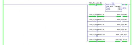
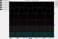
As you are using up one timer already you may as well try to make use of the .ACC bits in a timer. You are stuck to an on-off ratio of 1 and the clock signals aren't particularly accurate. Suggestions to improve the quality of the clock signal are welcome ;)

The logic needed is minimal and the provided clock signals are good enough to indicate multiple states by flashing some lights.


Oscillator.jpg

Oscillator_Trend.jpg
 

Similar Topics

I'm fairly new to Rockwell software, I've had some basic training in the past but nothing too advanced. My company and I use Reliable products for...
Replies
11
Views
318
Hi all, I am having issues accessing my Cimplicity software - the site code changed after re-install and I am no longer able to attain a new key...
Replies
10
Views
158
Good day all! Can someone help me with the procedure to update Beijers E700 firmware? The Panel I am working on is firmware 2.04v and I would...
Replies
1
Views
68
Hello nice to meet you, im new in here, I'm currently trying to convert code written in STL for a S7-400 to SCL for an S7-1500, because when i run...
Replies
5
Views
317
Back
Top Bottom