Timer preset question for SLC500

ceilingwalker

Lifetime Supporting Member
Join Date
Mar 2010
Location
Phoenix, AZ
Posts
1,586
Good day all. I have a Quick Panel Jr and a SLC500 with 5/03 processor. I'm creating a timer instruction that the preset will be set by the operator at the HMI (Quick Panel Jr.). I have the base set to 1-second. I would like to be able to have operator's input amounts to the nearest 1/2 hour. For example: the operator will put 1 for one hour, 2 for two hours,1.5forone and one-half hours, .5 for one half-hour, etc... . How to I set the time base so that when the operator selects 1, it will tell the PLC 60 seconds? I tried creating a multiply instruction so that, whatver the operator entered, it would multiply it by 3660 (seconds in one hour), and then move that value to the timers' preset. I keep getting overflow errors. Does anyone have a suggestion as to how I can accomplish this? Thanks much.
 
I would use a compare statement if there isn't a lot of numbers.

What is the maximum number of hours that will need to be entered? Any time less than 9 hours by your way should work (but I assumed there was 3600 seconds in an hour). That is assuming that you use a 1 second time base.
 
I have the tag from the HMI as N59:, for the operator to enter the desired amount of time. I then have the MUl instruction for converting the time requested by the operator in hours, to the time base, which is seconds. For some reason, I get a minor fault with the first scan. Should I use an "F" address instead of an "N" address?
 
If the operator enters "2.5" what does the target 'N' register contain?

Does N59 actually mean N7:59?


If an entry of "2.5" gives 25 in the target register then your MUL command should multiply the N register by 360 to arrive at total seconds.
 
If the operator enters "2.5" what does the target 'N' register contain?

Does N59 actually mean N7:59?


If an entry of "2.5" gives 25 in the target register then your MUL command should multiply the N register by 360 to arrive at total seconds.

The integer files are a little confusing to me. I only used it becasue it seemed the easiest way to create a tag for the HMI that could handle a large number. Right now operator's have to enter time in seconds, leaving a lot of room for an accident becasue of incorrect math. That's why I was wondering if I should use an "F" file instead (for the input from the HMI). I don't understand what you mean by "Does N59 actually mean N7:59?".
 
You mentioned that the HMI has a tag "N59:". What is the PLC address associated with this tag? N59, by itself, is not a valid address in the PLC.

Targeting a Float would be ok. Then the multiply would work correctly (Number of hours times 3600). Use the timer's preset (or any integer) as a destination.
 
It is N59:0. Is it possible to have have the HMI write right to the Float, or will I need to have it write to the N59:0 then move it to a float data file?
 
My copy of the Quickpanel software allowed setting a float (F8:0) as the target and compiled without any warnings. I don't have a system to check it out with though.

But using the Quickpanel, writing to an Integer, if you set a decimal position (let's say 1 decimal) then a display of "1.5" would end up in the integer file as 15. "2.0" would show up as "20". That's I was asking about the appearance in the target location.

Using that format you would multiply the contents of the integer file by 360 to arrive at seconds.
 
Last edited:
You can't use a float for the preset. If the panel allows a float, in the PLC a line like MUL F8:0 3600 N59:0 should work. If you prefer to manipulate the integer directly, see if the panel allows a scale factor. With a scale factor of 10, the operator enters 2.5, and the panel actually sends 25. If that works try a scale of 3600. Depending on the software you may need 0.1 (or 0.0028). If the manual isn't clear about it just try it and see.
 
Here is a suggestion for a different approach. Make 4 separate Tags on the Quickpanel labeled .5, 1.5, 2.0, 2.5, (or whatever value you want). Put 4 timers in the SLC program. Set each one of them for the desired time value. Let the 4 tags write to their assigned bit (for example, B3:0/0 thru B3:0/3) in the SLC to start the timer assigned to it. Interlock the different timers so only one could be on at a time. That way it should simplify things for the operator.
I hope the idea is clear enough, it's a little hard for me to put it in words.
 
...Does anyone have a suggestion as to how I can accomplish this? Thanks much.
I would use a Multistate indicator and a function key that just scrolls through the options. The presets will be .5, 1.5, 2, and 2.5 hours.
0>>>.5
1>>>1.5
etc..
That way the operators can't enter the wrong value.

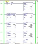
Adder.jpg
 

Similar Topics

Hi there I'm guessing this is a straightforward one but after much experimenting I've been unable to find an answer. The software is TIA V16...
Replies
5
Views
2,323
Processor: 1769-L30ER; Logix 5000: v32.02 I have an AOI that's been used in previous applications without issue, and have added a TON...
Replies
6
Views
2,739
Hello Folks, I am new to Direct Soft, but a customer has a program that need me to edit. It is a DL06. We have a TMR function (T4) that we want...
Replies
24
Views
5,571
I would like to use a numeric entry from a C-more HMI to change the preset in a timer in Do-More. How might I go about that? Thanks
Replies
1
Views
1,269
I have an array of UDTs in which is located a timer. I have made a page where I wish for the timer preset to be adjusted. There's just zeroes on...
Replies
0
Views
1,073
Back
Top Bottom