High speed counter module IC693APU300J

jcp

Member
Join Date
Feb 2010
Location
Multan
Posts
369
Hi friends;
I have a high speed counter module IC693APU300J. In our system the frequency range is 0 to 12000 HZ and the amplitude range is 0.5 v to 10V. I can not understand how i fix and configure the module in the system to read the correct frequency from Gas flow meter, and rotational frequency of gas turbine from Magnetic pickup.
Kindly guide me how i connect the Mag pickup wires to the module, configration and how i apply in ladder logic?
Regards
 
Sir; I have i read it but can not understand as implement in my system.
System is
RPM measured by Magenetic pickup its resistance is near about 210 ohm and give me approximatly sinewave with amplitude of 1 to 12 volt and frequency is 11520 HZ.
Is it possible i connect directly with module?
If yes please guide me about the configration.
About analog module its faulty and i arrage new one in one and two days.
Thanking you i will remain
 
With no jumper connected between terminals 13 and 15 (Page 2-7), the module is set for 10 - 30 VDC range. Specifications (Page 1 -8) indictae that when jumpered for 10 - 30 VDC the ON threshold for inputs is 8.0 volts and the OFF threshold is 2.4 volts. When the signal from your mag pickup exceeds 8.0 volts the module will detect a count pulse. The signal must then drop below 2.4 volts before the module will detect another count pulse.

I suggest you configure the module as Type B. Leave all other settings at default values. Chapter 5 explains each of the configuration choices.

Connect the mag pickup signal to terminal 1 and DC- to terminal 13.

When the mag pickup is working you should see the frequency in the second %AI word assigned to the module. You should see the count accumulating in the fourth and fifth %AI words (32-bit).
 
Hi
Thanks for help. But i am little confuse after read out the answer. 10 to 30VDC and u say 2.4V off thr and 8.0V on ther values for count.Is it DC or AC value?
Secondly i said before the voltage level i get from the Mag pick up is 1 to 12 volt but no major change in volts when speed increas or decrease. The voltage depends on the Gap between gear and tip of probe. Suppose Turbine runnnig at contineous on 11000 HZ and voltage is 9.8 Volt AC.
is it measure because no change in voltage amplitude and frequcency for this example.
when i increase the speed frequency change from 1000 to 11500 but voltage is 9.8 to 10.1 volt.
As you know the magnetic pickup function to measure the speed of any rotating machine.
In my experience i think a very little change in amplitude but in frequency major change occur when speed increase or decrease.
Am i right? please guide me how it works if i am wrong?
Because In OLd system when i calibrate the Black boxces from Continental control corporation i apply the 10 volt AC and change the frequency to calibrate diffrent points at desired frequency.
I also explain that in 2000 a user use this module with FTV counter from JAQUET company. I visit a company where same module is used to measure the GAS Turbine speed.
Connections are as under
Mag pickup connects to FTV UP counter and from the counter the wires connect to HSC module.
But i have no FTV counter so i try to connect this module directly to the Mag pickup and read frequency at which turbine rotates.
I also think that you say 2.4 to 8.0 v DC but i got AC can i put a diode in one line to make it half wave pulsating DC?
Regards
 
The 90-30 high speed counter requires a DC pulse signal. What did you read in the manual that made you think it could work with AC? Don't connect an AC signal to it and expect it to work. Don't waste time trying to condition the output from the existing AC sensor. Get the right sensor.
 
Ok, sensor can not be changed. is there any other solution?
I need the proper guide line from you to achive the task.
I say sensor can not be changed because it supplied from the manufacture according to its diameter which we fix on turbine gear teeths.
Please guide me with Mag pickup how i read the frequency at which turbine rotates? I follow your sugesstion? which counter or converter or may be module but cheep as well please
 
Hi
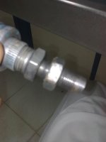
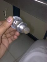
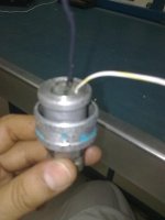
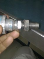
Sir steve i attached the images of speed sensor which we used to measure the speed of gas turbine. The documentation is not available because it came with gas turbine package from Solar Turbines INC. but i explain the function as follows
it contains a coil and magnet. when teeths on the gear passes it generate frequency as propotional to the gear rotation speed and the voltage amplitude is about 12 volt at rated speed. The amplitude of the voltage dependes on the gap between the tip of the sensor and the gear which is near about 40 to 50 tho(Thousand of inch).
Hopefully now u guide me about my task.
Reagrds

DTA0110.jpg DTA0111.jpg DTA0113.jpg DTA0114.jpg
 
SIr;
There is no option to supply it. It generates AC when gear rotate by the rule of Electromagnetic Induction by Farday's Law.
Regards
 
Sir Micky;
Do u read all the post. I do not required a under speed and over speed over protection. I want to use HFC module which i mention above to read the frequency by using this module with PLC90-30 series.
 
Check out this. It will explain the sensor type and uses.
Hall effect sensor may require analog circuitry to be interfaced to microprocessors. These interfaces may include input diagnostics, fault protection for transient conditions, and short/open circuit detection. It may also provide and monitor the current to the hall effect sensor itself. There are precision IC products available to handle these features.
http://en.wikipedia.org/wiki/Hall_effect_sensor

I had same problem years ago. Bought hz to pulse converter to attach to HSC.
 
Last edited:
After further thought I remember I did not use HSC but instead the converter was [HZ to ma] and I connected it to Analog Card.
 

Similar Topics

Hello Folks, Has anyone configured a Momentum high speed counter on Unity 13.1. We need the wiring diagram for Momentum High speed counter and...
Replies
0
Views
76
i am bench testing a 1734 -VHSC24 Point I/O High Speed counter module, i cannot find any examples of wiring the outputs from the module. does...
Replies
4
Views
1,385
Hello guys, I have created a program where I count the high speed inputs of a flowmeter and create pulses per second to check the flowrate. Next I...
Replies
5
Views
1,784
Hello to all, I don't have to much experience in the PLC. I'm using the Studio 5000 v32.03 We are trying to measure the length of a product, in...
Replies
3
Views
1,126
Does anyone know how to set the output window on-off values on the fly without having to inhibit the module? I could of sworn when I first started...
Replies
11
Views
2,377
Back
Top Bottom