programming Micrologix 1200 with RSLogix

chriswarrn

Member
Join Date
Dec 2003
Posts
24
I'm trying to write a program to measure the Feet Per Minute of a conveyor. I would like to display the FPM at least once every 2 seconds or so. I want to use a prox switch to sense the teeth on the sprocket. Each leading-edge pulse of the prox (the length of each prox pulse depends on the FPM of the conveyor) will move the accumulated value of a free-running timer to an address, and then reset the timer. Then I'll just do a little math and display the measured FPM.
Maybe I'm trying to do this the hard way, but I can't figure out how to move the timer value before the timer gets reset. The timer reset command is always performed before the MOV. The address I'm using always reads zero.
ANY ideas will be gr8ly appreciated.
 
The timer reset command is always performed before the MOV

That's the problem. A timer reset command always zeroes out the accumulated value in the timer.

If you perform the MOV just before the RES, you should get the accumulated value. You could even put the RES on a branch of the same rung if you want.
 
Just a thought, couldnt you make the timer retentive? Timer activates , EN also triggers a bit to show it has been running (WAS). True conditions go false, timer stops. Then you use, not EN, and WAS with a one-shot to perform the move and reset the timer and WAS. This make sense?

I guess that could get hairy depending on scan time and speed of the conveyor but he was ok with a 2 sec update. Technically one scan should make the data move after timer stops and unless the sprocket is moving very fast it should be able to update way under 2 secs unless he has a timer set to trigger the update every 2 secs, if that is so then I am sure it would work.

You have to pardon me, I have a tendency to think out loud.

Now that I have thought about this what Ken said does the same thing with less effort...ie put the MOV instruction on a rung prior to the RES and the data should move before it resets the timer.
 
Last edited:
Putting the RES before the MOV was the first thing I tried. I even put the RES as the last rung, but I need to move the timer value and reset the timer under the same true rung conditions, but doing so always resets the timer first before the move occurs no matter where in the logic I put the commands.

Apparently, the processor performs the RES immediately on a false-to-true transition of the rung, but doesn't perform the MOV until it finishes the scan....???
 
I need to move the timer value and reset the timer under the same true rung conditions
That can be a problem, scans work on inputs first then actions then outputs...if you reset the timer on same rung as MOV then it wont make the MOV. QUESTION: IS RES on top branch of rung or MOV, that may make a difference. There are time/scan issues here I am sure.

Try my method with a RTO, you must have RES after the MOV. Using the retentive timer should allow time for the Move then Reset after the move has been made, if needed determine scan time and create a reset timer that allows for a scan before its reset. Technically this shouldnt take much more time than it does to pass over a tooth or 2 on the gear.
 
Last edited:
I don't know why you can't MOV before you RST, but I don't have a MicroLogix laying around to prove it out. I have a feeling the timer is getting reset by the timer rung going false. Another reason to try Ron's retentive timer idea.

I posted some code at Ron's to display 'cycles per minute'. You would use different math to determine 'feet per minute', but it's the same general idea. Click HERE to read the thread at Ron's, but here's a quick translation to A-B that should work... :confused:

| PROX_SWITCH
|----] [--------------------------------------( 1-SHOT )
|
| 1-SHOT TOGGLE +--------------------+
|----] [------] [-----------------| DIV |
| | Source A: 6000 |
| | Source B: T4:0.ACC |
| | Dest: N7:0 |
| +--------------------+
| 1-SHOT TOGGLE +--------------------+
|----] [------]/[-----------------| DIV |
| | Source A: 6000 |
| | Source B: T4:1.ACC |
| | Dest: N7:0 |
| +--------------------+
| 1-SHOT TOGGLE
|----] [------]/[-----+-----------------------( TOGGLE )
| |
| 1-SHOT TOGGLE |
|----]/[------] [-----+
|
| TOGGLE +-----------------+
|----] [-----------------------------| TON |
| | Timer: T4:0 |
| | Time Base: 0.01 |
| | Preset: 9999 |
| +-----------------+
| TOGGLE +-----------------+
|----]/[-----------------------------| TON |
| | Timer: T4:1 |
| | Time Base: 0.01 |
| | Preset: 9999 |
| +-----------------+


This calculates 'cycles per minute' by measuring the time from 'leading edge' to 'leading edge' of the same prox. switch (one total cycle). It use two timers to time alternate cycles. Again, you'll use different math to calculate FPM. This version just divides the total cycle time into 60 (actually 6000 with the 0.01 time base) to get 'cycles per minute'. The 'cycles per minute' value resides in N7:0.

You would want to add to this so it will only operate while the sprocket is turning 'at speed' to prevent 'weird' CPM values... ;)

Hope this helps... :D

beerchug

-Eric
 
rsdoran said:

That can be a problem, scans work on inputs first then actions then outputs...

This is true for the state of an input during a scan(they don't update without doing a immediate input), and the turning on/off of an output during the scan(they don't update without doing an immediate output). But changes to the output image data table as well as any other data table elements take effect immediately at the time of processing the particular rung during the scan. This includes timer values and status bits, N files, B files, all of them.

rsdoran said:
if you reset the timer on same rung as MOV then it wont make the MOV.

It would make the MOV as long as the MOV happens first. Are you using a RTO or TON? If you are using a TON the rung conditions have to be true for the TON during the scan that the MOV takes place, because when the TON preceding rung conditions go false the timer automatically resets.
 
93 thanks that was actually what I was trying to say but guess it didnt come out exactly right. I have had some issues simialar to this in the past so found it more convienent to use an RTO to retain the value for at least one scan longer. I have done things similar with a TON's but guess it all depends on the situation what you use, at least for me it does.
 
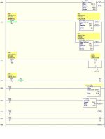
I wrote this little routine just to prove I'm a novice, and try to make the ACC value move before the timer resets....the counter is just for checking for one shot pulses.... No matter where I move the MOV or RES, the moved ACC value is always zero. I'm missing something.
 
Maybe I should attach the file BEFORE I click submit...except I can't figure out how to capture the ladder screen...HELP!
 
Here you go. This worked for me. I tested this on a MicroLogix 1000 but should woke on your 1200

time mov res.jpg
 
Last edited:
except I can't figure out how to capture the ladder screen...HELP!


You just need to save a screen capture to your hard drive as a picture type file, then Browse for it with the "Attach File" option at the bottom of the new reply composition screen.
 
Like I said...I just proved how little I know. Thanks Bob. I was trying to set up a flip-flop when all I needed was a simple one-shot. Thanks for everyone's input. This site is just what we once-a-year programmers need...but just for the record this is what DOESN'T work...

test123.jpg
 
Chris,

B3:8/11 is being energized whenever T14:0 is timing (per Rung 2 & 3). You need to one-shot this (your unlatch at the bottom doesn't work whenever T14:0 is timing).

Bob O's construction should work fine.

Marc
 

Similar Topics

Hi, The MicroLogix 1200 has a Com 0 port and a "HMI/programming port". When looking at the PLC, there is a port on the left side and a port on...
Replies
6
Views
1,744
In micrologix1200 I have only one communication channel so that I do not unable to configure the PLC with Modbus rtu slave driver without losing...
Replies
9
Views
4,262
I need some help with a plc I am working on.... I would like to have 4 push buttons send different analog output signals at one output channel...
Replies
13
Views
4,068
Hello, Does anyone know if can use a : TSXCUSB48 + TSXCRJMD2 (Telemecanique Cables, the first one is a USB->RS485 and the second one is a...
Replies
3
Views
2,145
I have a customer that has equipment that has AB micrologix 1200 plc installed in it. I am looking for a way to obtain the software for it. I was...
Replies
3
Views
2,146
Back
Top Bottom