Request Wiring 4-wire PT100 sensor to Siemens SM334

MOeZ

Lifetime Supporting Member
Join Date
Nov 2009
Location
singapore
Posts
101
Dear All,

I would like to connect 4 wire pt 100 connection to SM334-0KE00-0AB0 Unit Modules. In my hardware setup, firslty i configure measuring type R-4L. I connect PT100 sensor to channel 0 >> 2(red cable), 3(red cable), 4(white cable) and 5(white cable). my problem is i can see analogue values at channel 1 even though i connect in channel 0.

so i think, my hardware configuration is wrong. so i change to RTD-4L in hardware setup. After that i see out of ranges at channel 0 (32768) and channel 1(-32768) . So kindly advise me and any samples wiring will be very much appreciated and will be helpful for me, please!

I have s7 300 module data manual but i quite not understand about Pt100 4 wire connection.
 
"R-4L" is for resistance measuring, "RTD-4L" is for temperature reading of an RTD.

Most Siemens cards want unused channels jumpered out. Sometimes I've seen unused channels that are not jumpered (open) read the same as the channel next to it.

Your wiring seems correct.

Does this module have a hardware configuration jumper block(s), in the shape of a "+" on the side for each channel ?

Be aware (the manual says) that each set of channels (0&1, 2&3) must be used the same, temperature or resistance.
 
Thanks for answer!
So, i have to set R-4l for resistance measurement and My wiring is correct for PT100 4 wire connection? This module don't have hardware configuration Jumper blocks at side of module.

I only want to use channels 0 so i will jump out channel 1. Any suggestion on my wiring? i have still problems.

Bgrds,
 
Use "RTD-4L" for RTD's. When you change the settings, I like to cycle power to make sure they are changed and applied.

Do you have 24vdc connected to L+ and M ?

Check that there is nearly zero ohms between IC1+ & M0+ and also M0- & IC0-

Check resistance between M0+ & M0- for the RTD resistance.
 
Hello theDave2,

I will change and Check all as per your suggestion. I connected 24vdc correctly to this sm334 module. after i get results, i will let you know and let me come back to you please!
 
lets try this
moz-screenshot.png
http://support.automation.siemens.com/WW/llisapi.dll?func=cslib.csinfo&objId=27833057&load=treecontent&lang=en&siteid=cseus&aktprim=0&objaction=csview&extranet=standard&viewreg=WW
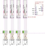
look at the wiring on the diagram

too lazy to draw it again
the current is from #2 red the measuring is #3 red and #4 white
now connect a wire to ground #7 white
short out #5 to #6 if not used
 
Many Thanks Shooter & theDave2,

Now my 4 wire PT100 sensor is working after measuring theDave2 suggestion. I got following readin
IC1+ & M0+ ... 110 Ohm (/* Should be 0 Ohm */)
M0- & IC0- ... 110 Ohm (/* Should be 0 Ohm */)
M0+ & M0- ... 0.6 Ohm (/* RTD resistance */)

So i did wrong wire connection. Change it Shooter's Suggestion. Now my AI card is working. Thanks
 
I have 4 wire RTD. I connected as per module. I ma using s7_1500_ai_8xu_i_rtd_tc st module. I connect my pt100 at 4 and 5 channel. two red wire at channel 4's 3pin and channel 5's 3 pin and two white wire at channel 4's 4pin and channel 5's 4pin.

All parameters are set but when I try to read it shows me 7FFF Hex. which is the error code for over flow.

I can not figure it out :(
 
S7_1500_AI read PT100

I have 4 wire RTD. I connected as per module. I ma using s7_1500_ai_8xu_i_rtd_tc st module. I connect my pt100 at 4 and 5 channel. two red wire at channel 4's 3pin and channel 5's 3 pin and two white wire at channel 4's 4pin and channel 5's 4pin.

All parameters are set but when I try to read it shows me 7FFF Hex. which is the error code for over flow.

I can not figure it out ;(
 
I have 4 wire RTD. I connected as per module. I ma using s7_1500_ai_8xu_i_rtd_tc st module. I connect my pt100 at 4 and 5 channel. two red wire at channel 4's 3pin and channel 5's 3 pin and two white wire at channel 4's 4pin and channel 5's 4pin.

i think wiring is wrong.
try reds to ch4 3rd and ch5 7th pin and whites to ch4 4th and ch5 8th pin
 

Similar Topics

So I had an odd request from a customer for the above. I have written the logic and tested it all in one PLC with only using 7 outputs and 7...
Replies
15
Views
427
Hello all, I hope you're all doing well. I am a complete newbie with a program sent by the manufacturer. I want to use it on a different plc, as...
Replies
3
Views
312
I know it is fairly simple to post a screenshot, but many of us have large screens, so perhaps y'all could take the time to trim those screenshots...
Replies
4
Views
511
Good afternoon all I'm a bit puzzled. 19 inch AB HMI. addressed 192.168.1.22. laptop 192.168.1.10. I can see it in Linx. I can download .mer to...
Replies
3
Views
623
Hi. I am trying to understand some old code for B&R 2005 PLC created in PG2000 software. There are procedures concerning axes but I cannot find...
Replies
2
Views
713
Back
Top Bottom