New guy with a simple question

abcgmeier

Member
Join Date
Apr 2011
Location
ALbuquerque New Mexico
Posts
5
Need some help please; I am new to the forum and possibly a little ignorant.
I need to use a relay to run a 12 DC actuator; the polarity needs to change to move it in and out of course.
My issue is the control for the actuator only provides a single input for the relay coils but reverses the polarity to drive a lower amp actuator directly using its built in relays.
So I need to energize the relays that drive the actuator based on the polarity applied to the coils.
12 vdc 15 amp load
Example using two relays
Relay 1 energizes when wire 1 is positive and wire 2 is negative. (Drives the actuater in)
Relay 2 energizes when wire 1 is negative and wire two is positive. Drive the actuator out
I was looking at latching relays but I need the actuator to stop when the coil is de-energized. My understanding is they do not.
Any ideas?
 
My issue is the control for the actuator only provides a single input for the relay coils but reverses the polarity to drive a lower amp actuator directly using its built in relays.


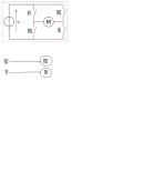
If I'm understanding your request correctly, you want a "H bridge".
http://en.wikipedia.org/wiki/H_bridge

In the pic I posted, imagine your polarity sensitive controller in place of the "M"

hbridge.jpg
 
What Vaugn has drawn for you is the standard reversing setup when line voltage is always the same and never changes polarity.

However you seem to indicate the power supply changes the polarity of the line to reverse the motor. Is this true?
IF so you do not need reversing contacts or multiple relays.
You may need only one relay to disconnect from power supply to give the power supply time to reverse polarity and - maybe more important - to let the motor come to a stop before energizing it in opposite direction.

Dan Bentler
 
Sorry if I am confusing the issue. I have a circuit board that controls a small DC actuator at 3 amps. It moves the actuator in and out by reversing the polarity on the two wires that lead to the actuator. It does this using two board mounted relays. This leaves me with the need to add another relay to handle a new 15 amp actuator between the board and the actuator, but the only thing I have to tell me to extend or contract the actuator is the two leads from the board that change polarity, but can only handle 3 amps.
This all done at 12 volts
 
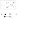
Shamelessly stealing and modifying Vaughn's excellent diagram, this is my illustration of Todster's suggestion. Y0 and Y1 being the ouputs from the interface board which currently exists.

hbridge.jpg
 
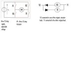
Here are my ideas on this project, shamelessly borrowing Vaughn's and Bernie's drawings and ideas. I could be wrong about what is the final task, so, if this doesn't help, just disregard. At 15 amps I believe an Adjustable Voltage Power Supply will work better than just a large potentiometer before the relay contacts.

hbridge-1.JPG
 
Last edited:
Ok, here is all of what I am doing. I am working on changing some of my solar panels into a tracker that moves with the sun. I want to make this something that my son and I can do together. The CB I have is a kit that uses photo resistors to track the sun and drive an actuator. Attached is the schematic for the kit, it is still in pieces waiting to be assembled. So I can change the relays, but I do not know what relays to use with the same pin foot print. I did miss read my amp requirements I have a 4.73 load at 12 volt DC. This is still more than the Axicom V23105-A5003-A201 is rated for.
Besides the board I am planning on adding some more features. I have wind activated switch spdt that I want to use to drive the panels to 0 degrees; this will protect them on high wind days. I am planning on using a two tilt switches operating opposite of each other to drive the actuator when the wind is high. I do not think I can trick this board to this so I was going to use relays to remove the board from the circuit and let the tilt switches take over until the wind dies down. So I was thinking that since I need relays to switch between the CB and the wind circuit I would not worry about the board relays.
I also want to add speed control to the actuator since tracking the sun need slow movements.
For my son I would like to try and build a circuit board from scratch to handle the added requirements, but the layout is kind of out of my experience. I understand the diodes so that is simple.
 
Last edited:

Similar Topics

I am just beginning my journey into plc programming and troubleshooting. I’ve downloaded the Logixpro simulator and I’m already stuck on the...
Replies
12
Views
2,260
Hey all! I recently purchased myself a Panelview Plus off of ebay and i was hoping that i could upgrade the firmware on it to Version 9 or so and...
Replies
7
Views
2,743
The website , www.theplcguy.com will soon be relinquished. It is available for purchase if you wish. I have not continued my interest in a day to...
Replies
18
Views
7,127
Howdy, I'm trying to connect to an SLC 5/04 using an old Toughbook running windows XP over the RS-232 port. Cable 1761-CBL-PM02 RSLinx Classic...
Replies
24
Views
5,541
Hello, I am making changes to a system that has a 5/04 processor and I come from the land of Mitsubishi so I have a question.... I have some...
Replies
26
Views
6,526
Back
Top Bottom