Ladder logic to Flowchart

robetere

Member
Join Date
Jun 2011
Location
Midlands
Posts
6
Hello, I have googled Ladder logic to Flowchart there is plenty of info for converting Flowchart to Ladder logic I was wondering if there are any guides or preferably freeware that will convert to flowchart.

Any help is greatly appreciated.
 
the best thing you can do is to understand Boolean algebra.
There are that many things happening in Ladder a simple conversion is not easy.
eg. when A is on, turn B ON
when A in ON, and C is OFF, Turn D ON.

the logic appears simple if there is not 300 rungs between A B C and D
 
My ladder logic program has 6 rungs although it has a timer and limit switches. Not sure if that makes things more difficult?
 
your ladder program for Assignment 3
is incorrect - converting it to flow chart is a time consumer.
what is the assignment task
why arent you using conditional statements instead of LIM.
Are there physical limit switches?

take the first rung
With rising edge of I1.1 ON
then latch B3:0.0 ON
Secong Rung - NOT SAVED TO PROCESSOR
When T4:0.DN is ON
OR
I1.2 is ON
Then Unlatch B3:0.0

Not hard But the Timer CCt has issues
 
So to convert it to flowchart would I do it rung by rung using Boolean algebra?
Yes, except the rung for the timer will not convert (very well) as a Boolean expression. A timer is an analog device, thus not binary or Boolean, so it is difficult to show its output as a "1" or "0", ON or OFF, YES or NO, and so on. You can have a line on your chart that Asks: "B3:0.0 ON?" Yes --> Run Timer T4:0; NO --> Do not run Timer T4:0.

You can also show the LIM instructions, whcih would show as Boolean expressions something like this: "T4:0.ACC between 1 and 32?" YES --> Do This; NO --> Do That Instead.
 
Last edited:
Firstly Thank you for taking time to look at my Program.

Its for a CCTV camera mount it has the need a calibration that has the following sequence:
30 secs Clockwise and Tilt Forward.
30 secs Anti Clockwise and Tilt backward.
15 sec Clockwise and Tilt Forward.

I have place a 1 sec gap between each stage.

It also requires manual control. Manual control disabled during Cal.

Rung 2 has been recently modified (Addition of I:1/2) hence it has not been downloaded to the processor. I have however seen the program work on a PLC (Although without I:1/2.).

Unfortunately there are no physical feedback switch from the mount.
 
Robetere,

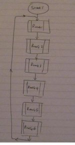
Good effort. Neat flowchart.

In real technical terms, your program "flow" does not return each loop or scan to the START block and re-latch B3:0/0.

Instead, once the timer is started, it is going all the way through the cycle, unless interrupted. Therefore, I think the 3 lines (Clockwise input Released, Anti Clockwise input Released, and Tilt Up Input Released) should feed back (not to Start) to the line on top of the Timer Finished block.

Even pickier, the 3 calibration functions are done serially, one after another, so maybe should be shown as such, with the end of the first one triggering the second one, and so on. If these functions need to be made parallel, then add two more indepencent timers.
 
Last edited:
Thanks for the feedback any improvements are welcomed. I'll work on Version 2 tomorrow.

You would think that there is some software out there that converts ladder logic into flowchart or even C or another computing language.
 
No problem, I try to help where I can.

Normally a flowchart is made first, then the program written to match the chart. The flowchart is supposed to be an aid to programming, to help keep on track. That may be why there are no programs to reverse-design a flowchart, simply because normally the flowchart is the starting point, not the end point.

But what you need to do is make the logic of the flowchart match the logic of your program. Previously it did not, showing that the 3 different calibration phases could be carried out in parallel, or independently from each other. But the program uses one timer and does the calibration serially, one phase after another. That is a big difference in logic. It could even be that in resolving the differences, you wil discover some things that should be changed in the program also.

The bottom line is the final flowchart should match the final program, and that can be accomplished by changing both.
 
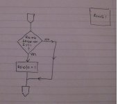
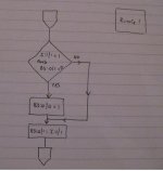
I would simplify the flowchart but make more of them. E.g. the whole program can be shown on one chart. Expand each rung onto it's own sub-flowchart.

fc1.jpg
 
(NB: I now notice the rungs are numbered 0 to 6)
The flow chart be done in a functional style - first rung:

fc2.JPG
 

Similar Topics

Hello, I am trying to replicate a piece of logic on the PLC5 onto an SEL RTAC. I am using ladder on SEL and FBD. I am having issue on the ladder...
Replies
11
Views
152
I have a machine which is undergoing upgradation. As part of the process two SEW drives are being replaced., existing Gen B with new Gen C. The...
Replies
3
Views
197
Good morning crew! Ok my logic works but I am missing something. When the start button is pushed it should like the red light for 4sec then shut...
Replies
13
Views
419
Working on project will update after it is completed.
Replies
2
Views
355
Can someone help me piece this problem together. I have a lot of it down I think but cannot seem to get it right. Probably an easy one for most on...
Replies
1
Views
303
Back
Top Bottom