What does this mean?

fishenguy

Member
Join Date
Nov 2007
Location
WESTERN PA
Posts
125
I have an AB 1746-NI8, analog input module. Currently there are 4 level sensors connected on channels 0 thru 3. These are using 4-20mA signals from a common power source.

What I want to do is connect two more 4-20mA signals to channels 4 and 5 using another power source.

What has me confused is the instructions:

The following diagram shows typical wiring for the 1746-NI8 module.
• Use shielded communication cable (Belden™ 8761) and keep length as short as
possible.
• Connect only one end of the cable shield to earth ground.
• Connect the shield drain wires for channels 0 to 3 to the top shield terminal.
• Shield terminals are internally connected to chassis ground which is connected to
earth ground via the SLC backplane.
• Single-ended source commons may be jumpered together at the terminal block.
• Channels are not isolated from each other.
• If a different signal source has an analog common, it cannot and must not be
connected to the module.
• Common mode voltage range is ±10.5 volts. The voltage between any two
terminals must be less than 15 volts.
• The module does not provide power for the analog inputs.
• Use a power supply that matches the transmitter (sensor) specifications.

I'm not sure if the underlined sentence pertains to what I'm doing. I'll connect the negitives to the two channels seperatly and also the two positives. I cannot use the same power source because it's comming rom another part of the plant.

Thanks for any help.

Dave
 
Greetings Dave ...

if you'll double-check that underlined item, I think you'll find that you copied it down wrong ... the book that I found gives that statement as "DIFFERENTIAL" rather than "DIFFERENT" ...

"differential" is one method of wiring – as opposed to the "single-ended" wiring method ...

take a look at page 3-7 (Adobe Reader 28 of 91) and the next several pages in the User Manual linked below ... see if any of the examples given match your setup ...

http://literature.rockwellautomation.com/idc/groups/literature/documents/um/1746-um020_-en-p.pdf

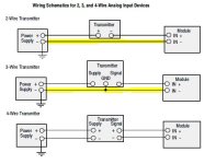
look in particular at the examples for wiring "differential" as opposed to "single-ended" ... and also at the examples shown for 2-wire, 3-wire, and 4-wire transmitters ... maybe that will help you out ...

to be completely honest, I personally don't know exactly what the book means when it says: "If a differential signal source has an analog common, it can not and must not be connected to the module." ...

specifically, I find the term: "has an analog common" to be confusing ... maybe some other forum member can shed some light on that ...

I will point out (just for discussion) this other statement from page 3-7: "Channels are not isolated from each other."

maybe (again, just a guess) that has something to do with the prohibition against connecting a "differential signal source which has an analog common" ...

please come back and let us know how this finally turns out ... personally I've never run into this particular question before ... (I say that knowing full-well that my distinguished colleague Mickey will probably be along soon – and post a link to a previous forum post that fully covers the topic) ...

hope this helps ... good luck with your project ...
 
Last edited:
Last edited:
They don't want the - (neg) side of the foreign power supply or the 4-20ma signal tied down to the - (neg) reference of the card.
 
They don't want the - (neg) side of the foreign power supply or the 4-20ma signal tied down to the - (neg) reference of the card.

well, yes, that does seem to make sense ...

but when you look at the schematics that they supply on page 3-8 (manual linked in my post above) then things sort-of-kind-of look like they might not be quite that simple after all ...

.


differential_common.JPG
 
As per diagram in page 28(3-7) you can feed common(Ground) of single power supply-feeding 4 different single ended signal sources,which are Transmitter/Sensor generating either Current or voltage in this case,to the module Ground.

But in order to connect a sensor to module 4 through 7,the common should come from only Transmitter/Sensor.

In other terms,If Dave wants to connect two sensors through 4 and 5 Channel;He needs to extend common(Ground) of 1st sensor(instead of common of Power Supply)to the negative of Channel 4.(This 1st sensor is overall 5th sensor and 1st as Differential signal source).
Common(Ground-Negative) of 2nd Sensor(overall 6th) must be connected to Negative of Channel 5.

A common Power supply can feed two different sensors through single common or separate common but the common(Ground) of that PS cannot/must not directly fed to Module's negative terminal/s.

Nirav
 
Thank you everyone for your replys. From the looks of the scematics that came with a new module, I determined that I can use up to 8 different power sources, as long as I don't tie any different ones together.

I checked for continuity between the screws on the terminal strip and found that they must not be tied together internally. I did this on the module currently in use (powered up).

I connected my two sets of signal wires up and turned it on. Everything is working....no smoke. I do have all my inputs fused.

I get all my guage readings on the HMI so apperently I'm good.

Thanks again, I appreciate everyone's input.

Dave
 
I have had problems trying to use more than one power supply on same input module. Like Mickey said, to prevent problems, use an isolator, or don't do it.
 
That always doesn't work

Long story - short version

Commissioning a job using an Ovation system that had a vendor supplied AB water treatment system tied in. what ever the mix-up, rather then remap the registers of the AB they decided to pass a few 4-20ma signals from the Ovation to the AB.

In most the refineries I've worked in we always had the DC- tied to earth but this was power generation and all DC Commons are floating as usual. But in this case when the 4-20ma signal - from the analog input card was tied down to the floating DC- of the AB rack it elevated the 24volts to 36 volts

When the AB "Start up Eng" showed up I had the 4-20ma + lifted from the drives and tried to tell him "We might have a problem with that ...... "

Will 3ea 755 Series input cards, a 755 Drive Main board, and a couple I/O points later he recommended we use a I/I to attempt to isolate the voltage. It isolated the current alright - but not the voltage. We still had the 36volts

Solution was we had to use Isolated Input cards on the 4ea 4-20ma signals coming over from the Ovation racks and the feed back signals from the 755 Drives. Additionally we used Isolated Output cards to operate the 755 Drives

Moral of the story ...

Remember how those Old School Techs always use to land the loop common and have the 4-29ma Sig taped off and then check the voltage before they drop it on a terminal during loop check ....
 

Similar Topics

The picture attached relates to the properties for the F9 key. Does anyone know what 'object number' refers to? What does 'object number' mean...
Replies
4
Views
719
I have used plenty of Fx 3U's but this is the first I have ever seen the ES-A. I can't find any refrence to it in any Mitsubishi literature. Looks...
Replies
6
Views
2,302
When I do a search of used devices (typically, to find a spare one I can use), this table appears, but I don't understand what "unpaired" means or...
Replies
7
Views
1,382
When I press F4 to convert the code, I get this message. What does it mean? Thanks
Replies
11
Views
2,545
Back
Top Bottom