scp for pid

Buzzen

Member
Join Date
Apr 2010
Location
stockton, ca
Posts
132
is it necessary to scale a process variable before the pid loop. I will be using a flow meter with a 4-20ma output to control a vfd.
 
Don't overwhelm us with details. ;) Generally, if you want, you don't have to. I do, because it make it easier to keep track of everything. Your SPs for instance will be to be scaled to something the PID understands.
 
What controller are you using ? Because you mentioned the "SCP" instruction it sounds like an Allen-Bradley SLC-500 or MicroLogix controller.

Many A-B analog input modules have the option to represent the full range of the channel as a value between 0 and 16383. Usually this is called "Scaled for PID" mode because that's the numeric span used by the PID equation for the Setpoint and the Process Variable.

So the second question is "what input module are you using" ?
 
Hey Ken,
[/"what input module are you using" ? The controller is a 1746-nI16I. The reason I asked about the scaling is because the light for channel status keeps blinking. I went to check the input at a bit level and found that 14 and 15 had a one. Which the book says means over-range detected. I will try the channel config menu you recommended and let u know if it works.
 
Buzzen,

Has it been working in the past? If so, it is probably not a scaling problem. If it is a new program, then yes, check the scaling.
 
Yes it is a new program, okay I will work with the scaling. I tried tuning the scaling and nothing works. The second thing I was wondering is that do you have to enable every channel or does rs take care of that when you read I/O configue?
 
If you get an Out-of-Range errror, most likely your values are too large for the PID instruction (larger number than that instruction can handle).

Which option did you choose for your Analog Input module configuration, PID or Engineering units?

Here is an example to set up an analog input module for PID Scaling. Notice that even though this is an Input module, you "configure" it by writing to an Output word for the Slot that the module is plugged into.

ANALOG INPUT SCALING FOR PID.jpg
 
Last edited:
now does happen manually or auto
????

I do not understand the question.

The analog module configuration 16-bit word value is determined by the options that you choose (see manual).

The PID Auto or Manual mode is set by a bit value in one of the PID Setup words, controlled by your program.

PID: Status Indicators
The following status indicators associated with the PID instruction are listed as flags on the right side of the PID Setup screen. Access this screen by clicking Setup Screen on the PID instruction.

AM Auto/Manual Bit (word 0, bit 1) Specifies automatic operation when it is cleared and manual operation when it is set. This bit can be set or cleared by instructions in your ladder program.
Rockwell Software 2000
 
Last edited:
Okay,
I was wondering if the processor adds the logic to the program itself like the first pass bit. I have a rung that has a copy file addressed to Source #N9:0
Dest. #O:11.0 that is associated with the input card initialization. I didn't clarify very well my apologies. My question is when you pick options under the IO configuration of the program click on slot 11, click on configure, click the channel you want. When you do this will it add the necessary logic to the program? Like if I were to choose scale for PID>
 
When you do this will it add the necessary logic to the program? Like if I were to choose scale for PID>
Will RSLogix add "necessary logic"? Well, I have never been able to get it to add anything. I always have to do it the hard way, adding logic as needed to do the job. Maybe someone knows a short cut.

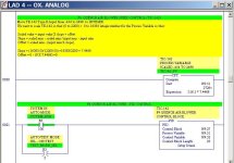
Here is an example of scaling a temperature input (I:16.1) to the range of 0-16383 for use in a PID block Process Variable (N9:51). I also had to scale the Control Variable N9:52 from 0-100% to 0-16383, on Rung 19 right above the picture.

PID Scaling Example.jpg
 
Last edited:
Wow awesome,
thanks for the professional courtesy there I really appreciate it that will help with my scaling for my HMI I am programming also. The problem that I had was the light kept blinking. What was going on I had only one ma signal going to only one channel. I had three other channels enabled that were associated with that light. I disabled the other channels and now no blinking light.....embarrassing!
 
Here's another one. I need to scale control variable for an output to vfd. Now does the control variable come off the pid as a percentage or as a 0-16383. If so could I use the above formula to display my flow as a number that can display on a HMI. My flow are 100-800ml/m
 
Here is an example of scaling a PID output so that it is the proper range for the analog output module. O:13.0 is a 4-20 mA output to a VFD motor drive.

Now does the control variable come off the pid as a percentage or as a 0-16383?
The CV from a PID is in the range of 0 to 16383 (represents 0 to 100%). You can change it, in the PID Setup Screen, to be anything from 0 up to 16383. The problem is that an analog output module uses a different range, so the PID output must be scaled.

PID Output Scaling to VFD.jpg
 
Last edited:

Similar Topics

I know a lot has been covered here regarding this issues but yet i still get lost. i am using these analogue cards 1. 1746-NI8 configured for...
Replies
6
Views
1,893
Hi, I have a micrologix 1400 with a 1762-IT4 module. I have channels 1 and 2 set up for "Scaled for PID" because I am using a PID to control...
Replies
5
Views
4,884
I need very simple example for pid and scp instruction, in allen bradley Micrologics PID loop for Tempreture control.. plz help me I am new in in...
Replies
0
Views
1,561
Hello, I am replacing a pH probe that was determined to be bad in a waste water treatment system. I am replacing it with a 2-wire Aqua Metrix...
Replies
8
Views
1,450
Hi I have a PLC 5/40E which passes speeds to a number of machines via rio. Currently there is no scaling and the machines use look up tables...
Replies
2
Views
1,723
Back
Top Bottom