Please comment..

theripley

Member
Join Date
Jul 2008
Location
laguna
Posts
545
Hi,

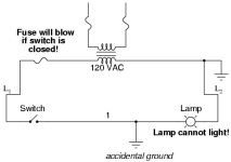
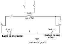
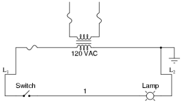
I have attached 3 photos of a circuit diagram. I posted this because I am in doubt of its correction especially that the L2 is being connected to ground.

It also confuses me what the accidental ground means & how it differs from the ground that L2 is connected with.

I hope you find time to comment. Thanks.
04006.png 04007.png 04008.png
 
Looks ok good to me.

The accidental ground is just showing you what would happen if there was a short to ground at that point(s) in the circuit.
 
This is normal. The neutral conductor is earthed which means if the active conductor accidentally shorts to ground (earth) it will cause the fuse to blow.
 
Let's say the primary is 480 volts.
1) Through capacitive and resistive coupling, there will be 480V on the secondary. 120V, floating at 277 volts above ground, if it's a standard Wye. Just a few mA, but there.
2) What happens if there's a primary to secondary short?
3) In Electron theory, we always want a source of electrons. That's the Earth.
Three reasons why the secondary must be grounded (Earthed). There's more. #2 is the most important.
In a true isolation transformer, there is a grounded plate between primary and secondary, preventing the problems with #1 and #2.
If the secondary coil is not earthed on the Neutral or 0v side the secondary + voltage could float, up or down and do damage to whatever it is wired to. I had this on several occaisions, when the istallation was done by the customer. I had to replace two baldour servo drives beacause the voltage was floating. I believe that earthing makes the neutral 0v and if it is not it can float thus giving a high or low voltage on the + side the difference between the two will remain the same so when testing across the coil the voltage read correct.
 
In the real world, you would NEVER put a switch on the grounded conductor. It is considered a "no-no", something that a considerate designer or engineer would not do, out of concern for their fellow humans. Most electrical codes prohibit a switch in this position.

PS: E, I see you are still searching and learning!
 
Last edited:

Similar Topics

I have attached logic which i made for the operation which is described below. This is the detail of what i need. Please have a look and let me if...
Replies
29
Views
5,320
Hi.. I've just completed Exercise 2 of Traffic Light simulation (using WordCompare). The one about Walk sign showing and blinking. Please...
Replies
2
Views
3,070
Hi , Where i can find Mitsubishi PLC Card end of line & replacement model details. i am looking for Q02CPU replacement model. Please advice. thanks
Replies
2
Views
110
Hello, I am trying to get a Yokogawa Hart pressure Transmitter and a Rosemount Temp Transmitter to read on a 1769-IF4 module on an L33ERM...
Replies
10
Views
352
Please help me, I have solve many week but still not solve it. I found trouble of factory talk studio when I set tag by browse address of OPC...
Replies
0
Views
114
Back
Top Bottom