Analog Input rslogix 5000

blown1fuse

Member
Join Date
Jul 2011
Location
alabama
Posts
15
I am very new to plc and need help with what element to insert in a rung for analog input I have AB 1769 IF4I/A analog input card. I want to show logic for a RTD analog input 4 to 20. The range and units are 0 to 100 deg C. I will need a alarm block to trigger an output to turn on a strobe light when HI limit is met. I cant find just a simple example anywhere. Any help is appreciated.
Thanks
Blownfuse
 
the module that you've listed doesn't work directly with RTD devices ... do you have a "transmitter" in the system? ... this would take the RTD signal and turn it into something that the module could accept ... (example: 4 to 20 milliamps) ...

if you have the transmitter, then attach your .ACD program file here to this thread and we'll be glad to tell you how to proceed ... note that you'll have to ZIP the file before you can attach it (forum rule) ...

and welcome to the forum ...

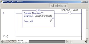
PS Edit ... depending on how you have the hardware arranged - and how the signals are scaled - your rung MIGHT be as simple as the one shown below ...

.

TEMP_ALARM.JPG
 
Last edited:
ACD file

OK I dont have much so far. I will add a few elements that I know I have. also I am interfacing to a panelview 1000. I know that this is additional to my original question but the alarm points will be set from panelview. Stand by I will try to attach the file. I do have RTD transmitters converting to 4 to 20 Ma. This should connect directly to the analog input card.
 
we've got a small problem ... you're working with version 19 of the software - and my copy of 19 is at the office ... I can look at it tonight IF you can do a "File Save As" operation and save it as an .L5K format ... ZIP that .L5K file and attach it and I'll "PROBABLY" be able to open it before bedtime ... or maybe some other forum member will happen by and help you out ... kind of quiet around here tonight - probably because of the holiday tomorrow ...
 
Last edited:
Analog element

If I can determine how to put in ladder logic a analog input in rslogix 5000. I want to input from my analog card 1769IF4I/A I will be connecting 4 to 20 input to the card. I want to add this to the ladder showing a range of 0 to 100 deg C. I then want to be able to set hi and low alarm points that trigger a output to energize a coil to turn on a strobe. I will be connecting a panel view 1000 for operator interface to ack alarms and adjust setpoints
 
first of all, you need to use valid tagnames ... (you can't have spaces, etc.) ... you could also just double-click on the XIC and use the Base tagname instead of an alias ... (example: Local:5:I.Ch0HAlarm) ...

then you need to nail down the scale for the input signals ... you're using "Engineering Units" which is probably going to come out as something like 4000 to 20000 ... somewhere along the line you'll probably want to convert that into a temperature reading ... what type of RTD are you using - and what range of values will you have for the input channel? ... in other words, 4 mA = what temperature? ... 20 mA = what temperature? ...

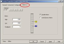
once you know all of that, you'll probably just want to go back to the "Alarms" tab for each of your input channels and set the High Alarm ...

tip: do NOT worry about the PanelView piece of the puzzle until you've got the PLC part working right ...

what kind of program is this anyway? ... it looks sort of like a student exercise since there's nothing here except for the RTD signals ... nothing wrong with that - we'll still be glad to help ... but the more we know about your project, the easier it will be for all of us ...

that's it for me for tonight ... wish I had more time to work with you ... hopefully this will give you at least SOME direction ... good luck with your project ...
 
Last edited:
Scp

I found it in the sample libary. As u can tell Im very new with plc programing. I seen in a post you had helping someone with simular issue that Im trying to figure out with the analog input. FYI my background as I/E tech I have never been in the programing side of things til now. I intend to learn but I have a long way to go. SCP (Scale With Parameters)
 
OK – so I didn't "create" it – I just mentioned it in another thread ...

anyway ... here's how to use one that you've found in the "Samples" area ...

(1) open the file that contains the existing Add-On Instruction ...

(2) right-click the Add-On Instruction that you want to use ...

(3) select Export Add-On Instruction from the popup menu ...

(4) give the Add-On Instruction a name that makes sense (example: SCP) ...

(5) save the Add-On Instruction to a folder that you can find later ...

(6) now open the project (program) where you want to use the Add-On Instruction ...

(7) right-click the Add-On Instructions folder ...

(8) select Import Add-On Instruction from the popup menu ...

(9) navigate to the Add-On Instruction you saved earlier ...

(10) highlight it and click Import ...

(11) now the Add-On Instruction should appear in the Add-On tab of your instruction toolbar ...

if this doesn't get you going, post again and someone else will be along shortly to help ... I'll be offline now for awhile ...

sorry if I've skipped a step - but I'm sort of in a hurry ...

good luck with your project ...
 
Last edited:
Analog input

Ron
Can you take a look at this logic I made for an analog input scaled to 0 to 200 with hi and low alarm trip points. I think this will work but I have a panelview 1000 that I think I read that the logic has to be all controller tags. Im not sure if this is the case but it looks like some of my tags show up as program tags only.
Can you advise?
 
well, you're getting closer ...

the first thing is that having the input module set up for "Engineering Units" won't give you a signal from 4 to 20 ... instead the signal will range from 4000 to 20000 ... the extra zeros are provided to give you better resolution ... changing the Input Min and Input Max settings in the SCP should take care of that particular issue ...

but ... going deeper ...

the formula in your SCP is wrong ... have you actually tested this out in a processor? ... go back over the math in the expression again ...

and ...

using the GRT and the LES comparisons is "technically" OK – but it won't work in practice ... the reason is that it's VERY seldom that an analog signal will stay dead-on-the-money at a given setpoint ... instead the signal usually "jitters" a little bit above and a little bit below ...

that means that your Low and High alarm bits will constantly be going on and off – and so will the strobe lamp ... you'll drive the operator totally nuts with this arrangement ...

in simplest terms, you're going to need to provide a "deadband" – in other words, a "close enough to the target" area where the alarms won't come on ...

one way of doing this is by giving some slack in the settings for the comparison statements ... another way is to feed the signal into a timer (or two) and only turn on the alarm when the signal has been too high – or too low – for some specified amount of time ...

and you're correct about the signals needing to be scoped at the Controller Level in order for an HMI to read them ... you can probably fix this by just going offline - and then Cut each tag from the Program tag list – and then Paste it back into the Controller tag list ...

just for the record, I'll be leaving soon to go on a road-trip for about three or four weeks ... it's best that you not address your questions directly to me – since I won't have much time to help you out ... but there are many forum members who are more capable than I am ... they'll be glad to give you a hand ...

finally – take a look at the figure below ... you'll probably like the "built in" alarms once you experiment with them for a while ...

hope this helps ... good luck with your project ...
.


IF4I_alarm.JPG
 
Ok thanks for reply. I see now what you are talking about on the alarm set point. What I ment to have is a separate set point for the Hi and Low that is set by the HMI. This will eliminate the nuance alarming as long as set points are not on top of each other. I looked at the Card alarm set points but I need them to be adjustable from the HMI these look to be set in the card config and not changeable by HMI is this the case? I also see what you are talking about on the formula. This was copied straight from the samples that loaded with the software.
Here is what I think it should read to work with the 4000 to 20000 input
((input - 4000)/(input_max - input_min)*(Scaled_max - Scaled_min))= output
I just dont know how to change it to this formula. What do you think?
 

Similar Topics

I need to scale analog input. I'm using software RSLogix 5000 and analog card 1769-IF4XOF2. So I want to make scaling for current sensor...
Replies
4
Views
5,051
Hello all, First I'd like to say thank you for viewing my post. I need to learn how to scale an analog input on the RSLogix 5000 without doing so...
Replies
4
Views
6,238
can any one direct me to an example in lader logic of a 4 to 20 analog input. what element do I need to use?
Replies
3
Views
4,097
I'm having trouble calming down 2 Tempo Sonics. I'm using Studio 5000 CompactLogix my Raw value is jumping around from 8575.0 to 8755.0 at a...
Replies
30
Views
1,082
I cannot add SLC500 analog input tag (I: 8.3) to EZSeries Touch Panel Editor (V 5.3). I used all the listed tag datatype but it all says "Invalid...
Replies
10
Views
246
Back
Top Bottom