Scaling in RSLOGIX5000

ddeshi2

Member
Join Date
Dec 2010
Location
Baton Rouge
Posts
89
Hi all, This is my first PLC project and I'm trying to implement split range control. I have two valves for Air(LowAir and Large Air)and one flowmeter. Low Air valve is opened first (at low flow rates) and after sometime Large Air valve is opened (keeping the Low air valve opened) as required by the process. The low and high air valves are rated as :

Low Air flow - Min 2.5 SCFM, Max 25 SCFM
Large Air Flow - Min 2.5 SCFM, Max 850 SCFm

So, when I input a setpoint of 750 SCFM (through HMI) the Low Air valve slowly opens until I reach 25 SCFM (as it is rated max 25 SCFM (4 ma =2.5 scfm and 20ma = 25 SCFM???)) and once it is fully open the Large air valve is controlled to achieve a flow rate of 750 SCFM. I got stuck at scaling the I/O channels and PID parameters.
I'm attaching the program I have written so far (it is not the complete program) .

Also I'm attaching the pdf file of the program written for micrologix so that you can get a clear idea of what I'm talking about.

Thanks in advance!!
 
I don't mean to be critical here, I'm just checking, but are you sure that the customer actually intends the 2 valves to work that way? The more common way to control air flow with two different sized valves is described below:

Two controllers (FC-A and FC-B) control the amount of combustion air supplied to the main burner in order to ensure accuracy and controllability throughout the operating window of the unit.
FC-A accurately controls the total combustion air flow supplied to the main burner by swiftly adjusting the trim air control valve (FV-A). The setpoint of FC-A is the total combustion air demand FY-F. The controlled value is the measured combustion air flow FY-A (compensated for pressure and temperature).
At the same time, trim valve position controller FC-B controls the optimum trim valve position FV-A. From this position, the trim valve is able to react swiftly on air demand variations in both directions.
The output of FC-A to the trim valve is used as the process value for FC-B, adjusting the position of the main valve (FV-B). If FV-A travels open due to an increasing air demand, e.g. via the feedback control, FV-B follows at a slower pace (slower tuning). Upon the resulting increase in actual air flow, FV-A starts closing and returns towards its previous optimum position.

Hopefully that makes sense, basically when running the trim valve acts to help respond quickly to demand changes, while the main valve slowly acts to keep the trim at a half-open position so it can still react.
 
@ 2stepsforward

I'm new to process control. Is it a cascade control? Can you please explain this sentence .."At the same time, trim valve position controller FC-B controls the optimum trim valve position FV-A. From this position, the trim valve is able to react swiftly on air demand variations in both directions.".. what would be the setpoint for FC-B? Please I'm new to all this. Thank you!!
 
@ 2stepsforward

Thanks for the nice article. I have learned something new today. But I have few questions, not about the process, as to how implement this in Ladder logic using RSLogix 5000.

I have two control valves (small and large) and one flow meter (installed before the control valves). The control valves are rated for : small- Min 2.5 SCFM, Max 25 SCFM, large-Min 2.5 SCFM, Max 850 SCFm. So, according to the article the flowmeter reading will be the process variable (PV) for my Small valve PID. Setpoint (SP) would be total flow rate that I want to achieve (in my case 750 SCFM through HMI). Control Output value(CV) is given to the Small valve. The same CV is used as PV for Large Valve PID. It is mentioned in the article that the Setpoint of large valve should be 50% to control the position of Small valve. My question is how can we set the setpoint to 50% in PID in a ladder diagram? Can you please help. Also please correct me if I was wrong. Thank you!
 
@ Mickey

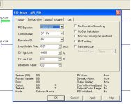
Yes, you have suggested me Split range control in one of the earlier posts and that was for SLC-500 PLC. But my boss wants to use controllogix and I got stuck at configuring the PID and 1756-IF16 Analog Input channel. Attached are the images of my PID configuration (small air valve)

Configuration:
PID Equation : Dependent
Control Action: SP-PV
Derivative of: PV
Loop Update time: 0.25 sec ( as I have used a preset value of 250ms on PID Timer to trigger the PID)
CV High Limit: 100% (not sure why))
CV Low Limit: 0% (not sure why)
Deadband Value: 0

Scaling:
Process variable
Unscaled Max: 16383 (because 20ma??)
Unscaled Min: 0(because 4ma)
Engineering Unit Max: 800 ( beacause Max. flow rate limit is 800 SCFM??)
Engineering unit Min: 0

Control Variable
Max. (at 100%): 16383 (not sure whether it is correct)
Min. (at 100%): 0

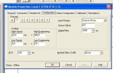
Analog channel scaling:

Channel 1:

Input range: 0-20ma (no 4-20ma option)
Scaling
High Signal: 20ma = High Engineering:800 (because of 800 SCFM)
Low Signal:4ma =Low Engineering: 0

Please correct me if I am wrong.

Small_Air_pid _config.JPG small_air_pid_scaling.JPG small_air_analog_channel.JPG
 

Attachments

  • CONTROL_SPLIT-6.pdf
    26.8 KB · Views: 21
My post in the other thread was suggesting what I call "Inching Control". ( I need to learn how to spell"suggest")
I am not a fan of "Split Range" with different size valves. You usually need different tuning parameters for each valve.
 
Last edited:
@ Mickey

Yes, you did mention about Inching control but I ignored it because the control valve person from Emerson said that our process can be implemented with Split Range control and my mind was full of split range control. But now I'm thinking of using Valve Position control or Inching control ( are they both the same?? I don't think so ...coz Inching control requires only one PID loop whereas Valve Position control requires two Pid loops).
 

Similar Topics

Hey guys, Normally I have an add in instruction that does this for me but the version of RSLogix I have (borrowed laptop) doesn’t have AOI’s so I...
Replies
19
Views
9,719
Hi Everyone, I am currently reverse engineering a hydraulic unit with a CompactLogix L35E and I have an issue with a Differential Pressure...
Replies
3
Views
4,233
Greetings All, I have a quick question regarding the PV scaling parameters in regards to PID Settings. I searched through all the manuals I...
Replies
5
Views
8,969
I want to measure the tank level and get the sensor output to the PLC. Below are the details : Tank Height =0 - 3m, the sensor is stalled 0,2m...
Replies
15
Views
588
Hi, I have a ControlLogix system with 1756-IF16 analogue inputs. I can't scale the inputs at the card as there is a requirement to facilitate...
Replies
14
Views
336
Back
Top Bottom