PLC DL05 encoder questions

ALIMARY15

Member
Join Date
Jul 2011
Location
italy
Posts
75
Good morning to everyone!
I am new to PLC programming and for our college exam we have been asked to program a micro PLC dl05 to make a linear axis control of machine.

I am planning for this purpose to use an incremental encoder to count the number of pulses to make the axis machine go in the required position.

I would like to know how can i store the encoder resolution into the plc memory?? lets say my resolution will be 0.1 mm how to convert and store this value into a V memory location?

thanks a lot
 
If the encoder is providing 1 pulse every .1 mm then your math operations must take that into account. If you wish to move 5 mm then you must expect 50 pulses, multiplying the number of millimeters by 10. You can store 10 (LD K10, OUT V2000 for example) into a single V memory register for use throughout the program. Then if you resolution changes you can then change just one location.

As further information, control of an axis which may change direction usually requires a quadrature type encoder. Please read up on them and the method of attachment in the manual for the DL05.

Be sure to understand the difference between BCD and Binary storage of numbers and their associated math operations.

Good luck on your project.

Thanks for your quick reply! I was actually planning to use the DL05 HSIO in Mode 20 that means Quad encoder reading for this project since i have already two quadrature signals from it.

I would like to ask one more question: how to represent the values into the plc? I am programming a HMI interface where the operator is supposed to enter the value (let's say 20 mm) of the movement wanted. At this point im supposed to choose which numeric representation is best suited to express this value that can be Unsigned Decimal 16 bit, HEX , or BCD. Which is best suited? and how to convert from one to another representation??
I wish to save this value into a memory location and then call it up into my ladder program to calculate the number of impulses the UDC counter must reach.

Thanks a lot for helping me out... I'm really new on those things of programming!

regards
 
Since the UDC will be using BCD numbers it will be best to stay with that as far as the position and count are concerned.

The BIN command is used to convert the accumulator's contents from BCD to the Binary format. The BCD command performs the opposite conversion.

How to you intend to actually command/actuate the movement?

The programming of the HMI can be left for later in the development. At that point the format of numbers which it will display or change will already be set and the HMI tags would then have to be set up accordingly. You may be able to export all your PLC tags in a format acceptable to the HMI programming package.

I'M sorry i don't understand well why the UDC is counting in BCD. I think i am missing some important theory here.. As written in the manual of the dl05 i started by configuring the Hsio module in mode 20 for quadrature mode. To do so I Loaded the costant K20 into the special location memory as appointed in the manual. I dont understand how the UDC is counting in BCD can you please explain me better? I understood that the UDC will go UP or DOWN in counting into the range 0-9999999. so this would be the number of impulses i count right?

In my project I am using a DC motor to move the axis. I command the motor on\off and the cw and cww directions using two rele that i command directly interfacing them with the plc. Then im supposed to have this HMI interface where the operator decide the displacement in which to move the axis.
 
All counters and timers in the DL series count in BCD. The fact that a double word count is limited to 99999999 should be evident. This does not mean that all calculations in your program have to be in BCD, but be aware that the UDC will present a BCD count.

When moving the axis be aware that it will not stop instantly. You may need to anticipate the stop distance in your calculations. This is easier if you have speed control as well as direction control, but it sounds like you don't have that.

You may wish to offer the operator these choices:

Move to an absolute position (for example - 50 mm from the zero position)
Move a relative amount (for example - 25 mm more than the current position)
Jog the axis (move while an operator button is held, provide two buttons)

Your code will have to determine, in the absolute mode, whether the desired position is less than or greater than (or possibly equal to) the current position and take that into account.
 
The easiest way to start on this is to hook up the motor such that it will turn the encoder. Attach them both to their respective points on the PLC. Enable counting. By forcing outputs run the motor in both directions. Watch the encoder count. Then write a simple rung to compare the encoder count with some number. Use it to run the motor until it is at or greater than that number. Then do the same in the opposite direction (equal to or less than the number) That will give you the best understanding of the core of your project..
 
I'M sorry i don't understand well why the UDC is counting in BCD. I think i am missing some important theory here..
Alimary, no, you are not missing any theory. When equipment is designed and built, it has certain characteristics built-in. These cannot be easily changed by the user. Bernie is saying that if a UDC Counter is built to display BCD numbers and no other type, then it may be easier for you to use BCD numbers in the other parts of your program (IF POSSIBLE). If not, then you will find that you have to make many conversions back-and-forth. My experience with the Automation Direct software is that for a majority of problems, I do have to make many conversions from different number systems to get the desiered results.
 
The easiest way to start on this is to hook up the motor such that it will turn the encoder. Attach them both to their respective points on the PLC. Enable counting. By forcing outputs run the motor in both directions. Watch the encoder count. Then write a simple rung to compare the encoder count with some number. Use it to run the motor until it is at or greater than that number. Then do the same in the opposite direction (equal to or less than the number) That will give you the best understanding of the core of your project..

Thank you so much for your suggestions! I am actually asked to make the axis move in a relative motion according to the operator requests. I am using a c-micro programming lcd screen for the interface and the value of the positioning will be stored in unsigned decimal.

What i understood is that if lets say the operator will introduce a displacement of 12.4 mm then it will be represented in the plc as 124 right? So how to convert into the BCD value?

in my ladder program I was thinking to use the following commands. Can anyone correct me if they are right or wrong?

LD K10 // i load the resolution value into the accumulator
OUT V2000 //and save it in this location
DIV V3000 // in V3000 i stored the value which is written from the c-micro panel so that i calculate the impulses expected as value of displacement/resolution
OUT V3005 // i then store the result in this location that i use then to check the number of pulses in the UDC.

is this calculation correct for interfacing then with the UDC counter?
I am sorry my questions may seem stupid but I simply loose myself into the numbering stuffs!

Thank you so much
 
The CMore Micro can be programmed to pick the count in BCD but show it with one decimal place noted. For example if the position count within the PLC is 123 the display can show that as 12.3.

In like manner the operator can enter 45.6 as a destination and the display can be set to write that to the PLC as 456 all in BCD. No conversions would be necessary, not even the multiplication by 10.

A note about the counts used by the UDC. They will be stored in two adjacent V memory registers because a single V memory register can only hold 0 - 9999 in BCD. There are specific instructions for performing math operations and comparisons on these double word values. For example, the single word multiply (MUL) becomes MULD when operating on the double word value. The numeric comparison operators which are inline can only work on single word values. You will need to refer to CMPD to compare double words.

BUT - if your count will not exceed 9999 (999.9 mm) then you don't have to worry about all this 'double' stuff (maybe I should have said that first). But just note where the cutoff is.

More as you progress.
 
Last edited:
The CMore Micro can be programmed to pick the count in BCD but show it with one decimal place noted. For example if the position count within the PLC is 123 the display can show that as 12.3.

In like manner the operator can enter 45.6 as a destination and the display can be set to write that to the PLC as 456 all in BCD. No conversions would be necessary, not even the multiplication by 10.

A note about the counts used by the UDC. They will be stored in two adjacent V memory registers because a single V memory register can only hold 0 - 9999 in BCD. There are specific instructions for performing math operations and comparisons on these double word values. For example, the single word multiply (MUL) becomes MULD when operating on the double word value. The numeric comparison operators which are inline can only work on single word values. You will need to refer to CMPD to compare double words.

BUT - if your count will not exceed 9999 (999.9 mm) then you don't have to worry about all this 'double' stuff (maybe I should have said that first). But just note where the cutoff is.

More as you progress.

Thank you so much for your precious help! I am now looking into the C micro software to set the value representation in the way you told me to the PLC! and yes I am actually using the DIVD and the CMPD instructions in my ladder!

Thank you so much i will try tomorw to upgrade on my project, and will come back to contact here if i need other help thank you so much because all the other people i was supposed to work with abandoned the project and now i am facing it alone and its kinda hard for me!

Regards and thanks again!!!
 
The CMore Micro can be programmed to pick the count in BCD but show it with one decimal place noted. For example if the position count within the PLC is 123 the display can show that as 12.3.

In like manner the operator can enter 45.6 as a destination and the display can be set to write that to the PLC as 456 all in BCD. No conversions would be necessary, not even the multiplication by 10.

A note about the counts used by the UDC. They will be stored in two adjacent V memory registers because a single V memory register can only hold 0 - 9999 in BCD. There are specific instructions for performing math operations and comparisons on these double word values. For example, the single word multiply (MUL) becomes MULD when operating on the double word value. The numeric comparison operators which are inline can only work on single word values. You will need to refer to CMPD to compare double words.

BUT - if your count will not exceed 9999 (999.9 mm) then you don't have to worry about all this 'double' stuff (maybe I should have said that first). But just note where the cutoff is.

More as you progress.
Excuse me again for disturbing you i was try to look into the C-program software.. I have set into the numeric entry options of the value that i want the value being displayed with a fractional number so like 14,3 , but how to tell the PLC how to read it??? where should i go in the C-more micro software?
thank you
 
A Big Note: dealing with the display is easier if it is the LAST THING you concern yourself with. When the PLC program is done you can export the various Nicknames you have given for the various registers you have used - BE SURE to give a meaningful nickname to each location you use in the PLC.

The following procedure is if you need to establish a name in the CMore and link it to a PLC location. It is not necessary that the name given in the CMore be the same as that use in development for the PLC - but it really helps in troubleshooting later. This is why I suggest finishing the PLC project and only then begin to design the display after exporting nicknames from the PLC software and importing them into the display software.

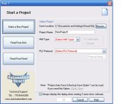
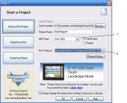
When you began the CMore Micro project you would have selected the type of PLC, the DL using K-Sequence is best (it can connect to many types).

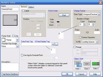
When creating the Numeric Entry you define a name for the location in the PLC

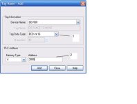
When you hit enter a screen comes up to ask about the location. Here I set BCD Int 16 which means a single word (or V location) interpreted as BCD. I note an address within the PLC. Of course you would enter the actual V memory area where you value is.

On returning I set the number of decimal points to show. This will automatically move the value and place the decimal point.

The final screen shows the control (you can change the size and position) with a dummy value filled in to show what it would look like.

01.jpg 02.jpg 03.jpg 04.jpg
 

Attachments

  • 05.bmp
    110.9 KB · Views: 13
Last edited:
A Big Note: dealing with the display is easier if it is the LAST THING you concern yourself with. When the PLC program is done you can export the various Nicknames you have given for the various registers you have used - BE SURE to give a meaningful nickname to each location you use in the PLC.

The following procedure is if you need to establish a name in the CMore and link it to a PLC location. It is not necessary that the name given in the CMore be the same as that use in development for the PLC - but it really helps in troubleshooting later. This is why I suggest finishing the PLC project and only then begin to design the display after exporting nicknames from the PLC software and importing them into the display software.

When you began the CMore Micro project you would have selected the type of PLC, the DL using K-Sequence is best (it can connect to many types).

When creating the Numeric Entry you define a name for the location in the PLC

When you hit enter a screen comes up to ask about the location. Here I set BCD Int 16 which means a single word (or V location) interpreted as BCD. I note an address within the PLC. Of course you would enter the actual V memory area where you value is.

On returning I set the number of decimal points to show. This will automatically move the value and place the decimal point.

The final screen shows the control (you can change the size and position) with a dummy value filled in to show what it would look like.


That's perfect thank you so much for your help i managed to fix everything now!!!!
I will keep now working on the porject,if new doubts will occour im gonna post here again!

thanks a lot again!
 

Similar Topics

Hi, I am trying to learn how to use my encoder with my PLC. I recently got a high-speed counter module (H0-CTRIO2) for my DirectLogic05 PLC. I...
Replies
5
Views
2,206
Good evening, I am working on a project where i am using a plc DL05 with an encoder to control an axis position. My encoder signals A and B, i...
Replies
8
Views
42,811
I've written a large program(300 rungs so far) and I am running into a problem with binary math. According to the DL05 manual DIVB and MULB says...
Replies
13
Views
3,465
I need to know if a high speed input card will be sufficient enough to pickup up the flow in a metering line with a flowmeter and a 24vdc pulsed...
Replies
21
Views
5,075
I am new to PLC's and am having trouble with the most basic step, connecting to my PLC. I am using a DL05, and Directsoft5 software (free 100word...
Replies
3
Views
5,617
Back
Top Bottom