HELP SIEMENS CPU315-2DP Analogue Module Wiring

NiCeBoY

Member
Join Date
Jul 2011
Location
Narre-Warren
Posts
37
Hi,
I am a student and trying to wire a Siemens CPU315-2DP Analogue Module with a 0-10V and 4-20mA sensors.

The Specs of the PLC are:
CPU315-2DP
SIMATIC S7-300 (315-2AF03-0Ab0)

AI-SM331-2x12bit
AO-SM332-2x12bit

There is digital input/output as well.. but they are working fine.

I have no idea which terminal to use and how to connect it.

Can anyone send ma a wiring diagram of this module, i can;t find it anywhere. or just help me by telling me which terminal to use.

Thanks in Advance..
 
331-7KB01 is the same as the 331-7KB02 in terms of wiring.

The inside of the lid of your card should also have a drawing showing you how to wire the card.
 
i'll give it a try on monday when i go back to uni.. and let you know here..

i dont know why this module has only 2 channel :(

2x12 bits :p

by the way, is there any configuration i need to to in the software?

Thanks
 
Uni is meant to give you a taste of things. A taste of what it is to work with a PLC, wiring one, the different kind of things you can do with a PLC, how analogs work.
Keeping this in mind and that most uni's need to watch their expenses, the 2x12bit is probably the cheapest solution to let you 'play around' with analogs.

Sadly enough there's still a huge step between what you see in uni and what you need to know on the job.

About your question:
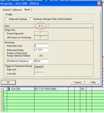
Obviously you know you need to create a Hardware configuration. In the HWconfig you need to select which type of analog you want to connect, the range of said analog etc. This is all done in the properties screen of said analog module.
IMPORTANT: Properties screen > In-/ouput tab (where you select the previously mentioned settings): There is a line saying 'Range selection module.' Next to it is a letter in brackets, going from [A] to [D]
These letters are very important. They refer to the placement of the range selection module. This is a black square module on the side of your analog card. It needs to be placed correctly before you attempt to wire the analogs. If done wrong, mismatch between configured setting and actual placement of this range selection module, you can blow up the card.
 
images


The side of the 6ES7 331 7KB01
Notice the one black square module? (and 3 empty sockets?)
It needs to be placed in the correct orientation to allow correct measurement of the analog value.
 
Ah i haven't seen that,
i'll remove it off the rack and check on monday.
thats a lot for all these infos mate.
very helpful..

After that i need to develop a scada interface to monitor..
 
images


The side of the 6ES7 331 7KB01
Notice the one black square module? (and 3 empty sockets?)
It needs to be placed in the correct orientation to allow correct measurement of the analog value.

I think you can select only current or only voltage signal.
That black square is for 2 channel?
 
I have no idea for now, i'll check on monday once i am at uni.
Its a 2x12 bit, so i think its only 2 channel.

by the way i'll need one channel for voltage and the other one for current.
so
1xcurrent
1xvoltage.


Hope this setting is possible.
 
Any idea how to set it so that 1 channel can read 4-20mA and the other Channel read 0-10 V ?

Cheers

You cannot configure the individual channels to be different. It is buried in the manual but it is written in such a generalised way (to cover all the modules) that it is easily missed. Things do become obvious though when you set the module parameters in h/w config (double click on the module in your rack).

You will have to convert the 4-20mA to 2.5-10v using a good old fashioned current to voltage transducer :)

poppp.JPG
 
As L D pointed out:
All Siemens analog modules are configured per set of 2 channels. (if there are exceptions, I haven't found em yet)

He also mentioned that despite this limitation, you should still be able to use both a 0-10V and a 4-20mA signal.

I'm not sure how much of this board you've browsed, but this is a real world problem (many examples here on the board), learning how to manage it now will save you time in the future.
 

Similar Topics

Hi all, i am the new controls guy at the plant and i have inherited a pc from the previous controls guy with Siemens tia portal version 16 and 17...
Replies
17
Views
638
Hi, I have a customer with a S7300 from around 2013 which they link to approx 25 inverters, 3 DP to DP converters and 5 IM153 remote I/O units...
Replies
8
Views
312
Hi all, First, thank you for reading the thread. So I had a task as the following: An up-counter must be programmed as part of a batch-counting...
Replies
7
Views
276
Hi I’m after some help , I have a plc program with a baumer verisens vision camera attached I have got the signals working ect but I have an...
Replies
9
Views
954
Good, Code Totalizer: IF ( Hour = 23) and ( Minute = 59) and ( Second = 59) THEN totalizerDay_previous : = totalizerDay; totalizerDay= 0; End_IF...
Replies
8
Views
1,552
Back
Top Bottom