You are using an out of date browser. It may not display this or other websites correctly.
You should upgrade or use an alternative browser.
You should upgrade or use an alternative browser.
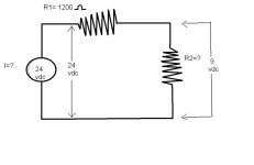
hey guys!!!!I want to see if I can help solve this problem
- Thread starter heliosaucedo
- Start date
Pretty simple.
Here's the formula you need.
V = I * R
Now you know the formula you need to solve this circuit, you'll need to know Kirchoff's Laws as well. But just the one that says the total voltage rises and drops in a loop equal 0.
Here's the formula you need.
V = I * R
Now you know the formula you need to solve this circuit, you'll need to know Kirchoff's Laws as well. But just the one that says the total voltage rises and drops in a loop equal 0.
Last edited:
bernie_carlton
Lifetime Supporting Member + Moderator
The formulas are ohms law.
1. You know the total voltage and how much is dropped across R2. What is left across R1?
2. Using Ohm's Law how much current is flowing through R1?
First #3. The same amount of current is flowing through R2. If that current is creating the voltage shown, what must the resistance be?
Alternate #3 - Knowing that the current in R1 is the same as in the total circuit how many ohms total would drop the total voltage? How many ohms are left for R2?
heliosaucedo
Member
OP
hey guys sorry but I do not understand them,I could help fix it, explaining step by step that's the first thing I do,thanks
1.you have a bowl with 24 apples in it
one person takes out 9 apples - what is left
2.the remaining apples can roll down a chute
- how fast - (curent)
- remaining apples divided by the r1
SORRY LEARN MATHS and transposition of formulai
one person takes out 9 apples - what is left
2.the remaining apples can roll down a chute
- how fast - (curent)
- remaining apples divided by the r1
SORRY LEARN MATHS and transposition of formulai
Mickey
Lifetime Supporting Member
Here's some light reading for you.
http://www.google.com/#hl=en&sugexp...l=&bav=on.2,or.r_gc.r_pw.&fp=5ebc4d519a3bd440
http://www.google.com/#hl=en&sugexp...l=&bav=on.2,or.r_gc.r_pw.&fp=5ebc4d519a3bd440
Tom Jenkins
Lifetime Supporting Member
Ian, when I saw your first answer I thought you made it way too easy for him - almost did his homework for him. Clearly I was wrong, and clearly no amount of help will be sufficient for this individual!
heliosaucedo
Member
OP
@ jvdcane waw let me surprise,but I am surprised coming from a person studied.I have 18 years and I have really wanted to learn,but there will always be people who believe more than others .and I could solve!! thank you all for your help. for something you learn
@ jvdcane waw let me surprise,but I am surprised coming from a person studied.I have 18 years and I have really wanted to learn,but there will always be people who believe more than others .and I could solve!! thank you all for your help. for something you learn
Glad it made ring a bell. Now if it were capacitors and an AC source, then I figure by now you'll have noticed you need inverse proportionality.
bernie_carlton
Lifetime Supporting Member + Moderator
Both resistors have 7 bumps in the schematic, doesn't that mean R1 = R2?
But one's horizontal and the other's vertical so they're 90 degrees out of phase. And since the second one's vertical the electrons pick up a little speed while falling (though they do get a little dizzy going through all the switchbacks.)
Similar Topics
How do you store values from an analogue signal conditioner using plc's
- Replies
- 4
- Views
- 2,423
Got a few questions for you gurus. Im in maintenance at michelin so i get a good bit of allen bradley fun. I recently came accross a siements...
- Replies
- 3
- Views
- 2,236
Does any one have a link on how a 12 lead genset can be configured to provide 3 phase 240 V plus 120V. Looking to possible buy a 640kW genset to...
- Replies
- 0
- Views
- 1,404
Just a small rant incase nobody downloaded or noticed yet.... but working on a new project in the latest version so I could test out FT Echo...
- Replies
- 7
- Views
- 1,168
Hey guys. First post, sorry if I'm doing this wrong.
Some of us were wondering about building trends in Studio 5000 for Compact or ControlLogix...
- Replies
- 6
- Views
- 931


