DeviceNet question

icehube

Member
Join Date
Nov 2005
Location
ohio
Posts
86
I am new to the devicenet and working on a trainer with it. I have configured it in rsentworx, but the question it how do i give it the run commands in the logic? Just kinda confused on that. I can upload the program and you can take a look if you want.thanks.
 
You need to be more specific about the components you are experimenting with Catalog numbers are a big help what type of platform are you working with? What devices you have connected to you Device Net Network.
 
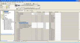
I have a devicenet scanner card and a flex 40 2hp drive. It is running on a L61 processor. Here is the program i hope it helps.
 
I can't see a drive on the DeviceNet network in the project, but there is one under the ControlNet network.

Look in Controller Tags under "TRAINER_1:O"
 
I have not done DeviceNet in Logix5000, but in a SLC or PLC-5, the most common practice is to have an unconditional OTE instruction in ladder logic so that if the PLC is in run mode, the scanner is in run mode. It is the very first bit in the scanner image IIRC. So look there for comments, and if that doesn't work for you, I am sure it is easy to find in the manual.
 
DeviceNet doesn't automatically generate tags associated with the network nodes like EtherNet/IP and ControlNet do.

There are two intermediate steps: The DeviceNet Scanner's Scanlist configuration, and the mapping of that Scanlist data into the I/O tables of the Scanner.

You need the *.DNT file from RSNetworx to see where in the 1756-DNB's data table the connection from the PowerFlex 40 drive is mapped.

It's probably at the very beginning of the scanlist, so you could proceed as though they were, or you could go through the DeviceNet Tag Generator.

One of the important things to remember is that the 1756-DNB's I/O table is composed of DINT elements (32 bits wide), while the PowerFlex 40's I/O words are INT (16 bit). Therefore typically both the Control and Reference words fit into a single DINT in the Output data table, and the Status and Feedback words fit into a single DINT in the Input data table.

This makes it a perfect opportunity to learn about how the COP instruction works with different sized arguments.

Use a COP of length 2 to copy the Input data table from the 1756-DNB's Module:I.Data[0] element to an INT[2] array tag.

Use a COP of length 1 to copy the Output data table from an INT[2] array tag to the 1756-DNB's Module:O.Data[0].

You'll find the meaning of each bit in the Control Word for the PowerFlex, as well as a description of the reference units, in the user manual.
 
Thanks ken, thats exactly what i was looking for. Just a little confusing. Thats why i wire and build this training module. To learn.
 

Similar Topics

I have Frontline NetDecoder Software and a 1784-U2DN in hopes of troubleshooting a DeviceNet issue. Randomly we have Nodes that stop communicating...
Replies
7
Views
2,447
When going "Online" with a running Devicenet network using RSNetworx through a 1770-KFD, will all physically connected nodes appear? I was under...
Replies
3
Views
1,613
Good Morning I have a question in regards to DevicNet We have a older system PLC 5/20 with a 1771 SDN B installed it communicated with a couple of...
Replies
14
Views
3,805
Hello This is my first post on this forum, so bear with me. I'm working with a DeviceNet system where there needs to be a transition on the trunk...
Replies
5
Views
2,506
Hi all...i am replacing a couple of motors from 3 to 5 hp....I am also replacing the drives. Do i need to remove the old ones from the scan list...
Replies
5
Views
2,766
Back
Top Bottom