Wiring a Pot

Tim Ganz

Member
Join Date
Dec 2010
Location
Dallas, Texas
Posts
685
I need some help wiring a pot to a drive.

The drive is a Allen Bradley Powerflex 700 VC in a working application that runs a conveyor. It gets it's speed command from analog input 1 which comes from a plc 5 and is based on the speed of a upstream conveyor.

The boss wants me to put a pot inline with this analog siganl so the operator at that conveyor can trim it. I know the center terminal of the pot is called the wiper i looked that up but I can't find what I need for wiring. This is a 10K single turn pot from the info on the package and it is a 0-10 volt signal coming to the drive.

Where and how would you always use all 3 terminal when making the pot control a drive itself?

Any info on pot wiring would help me learn.

Thank you for helping. :unsure:
 
How would you do it? Well, personally I wouldn't... If the operator needs to trim the speed of the conveyor, I would be looking at the reason for that and fixing it correctly instead of adding an essentially uncontrolled speed source (that WILL eventually come back to bite you!!)

But, technically -- you would take the existing output from the PLC and run it to one of the two outside terminals on the pot and connect the other to your DC- supply. Then take the signal from the wiper back to where your speed reference is currently connected to the VFD.

Understand -- all this will allow you to do will be to slow down the conveyor -- they'll never be able to make it run faster than the programmed speed from the PLC...
 
OZEE

From the plc i have a + and a - wire. Which one would I connect to the pot?

Can you help me understand the purpose of the other outside terminal back to the dc supply?

I am trying to understand how it works as well as wiring it up.

I want to understand for next time.
 
Most examples I found on the net use 1 outside terminal? So why does it have 2?

Thats where i am getting lost. If it were 2 termianls 1 input and 1 wiper that makes sense to me but the 3 terminal part is what I don't get?
 
I would recommend connecting the pot to an analog input of the PLC and allow it to be select-able and programmatically scale-able. If you hard wire it into the speed reference, every time that pot is touched or suffers damage, the conveyor command speed will change as rapidly as allowed by its accel decel settings. If you run it through the PLC, you can limit when and where this trim is applied, and further regulate its rate of change, detect when it is fudged up, etc.

Even if you have to spend $1000 to buy a PLC5 analog card, consider it money in the bank vs. putting an operator knob between the PLC and the drive.
 
Last edited:
OkiePC

We did suggest that and evn using the panelview that is right there with the operator but the plant engineer nad production manager did not want to hear it. They have a hard-On to do it this way.

And of course then my boss dumped it in my lap and said "Figure it Out and Make it Happen"
 
Can someone help m understand why we have 2 end terminals. I only see wiring power to one end termina then out of the wiper terminal?

Help me understand.
 
The PF70 and 700 allow a second pot wired in to the analog input #2 to be defined as a trim pot to the first analog input. You can program the exact range you want to control, or trim. Look in the manual for details, page 2-9, publication PFLEX-RM001G-EN-E.
 
Can someone help m understand why we have 2 end terminals. I only see wiring power to one end termina then out of the wiper terminal?

Help me understand.

First, do as RDS posts. Since it is a PF700, it has the ability to have a trim pot attached.

To understand (I would NOT do it this way at all) - as OZEE explained - you are going to create votlage divider circuit. You would need to run the existing 0-10 volt analog signal into the 2 end terminals, positive on 1 and negative on 3 (I'll call them 1 and 3 and the wiper will be terminal 2). So across terminals 1 and 3 will be the voltage signal. Then connect the wiper (terminal 2) to the analog input of the drive and terminal 3 to the analog common of the drive. Now you will have a circuit that will send out to the drive a signal from the maximum it sees all the way down to zero. As OZEE states, you will never be able to speed up the conveyor since you can not create more volts than you are actually getting. For example say the drive is getting 8 volts now. With the 10K pot in there, you will only be able to control it from 8 volts down to 0 volts with 1 turn.

potentiometer.jpg
 
Last edited:
Tell 'em that you can't wire a pot to the drive and give them a slider on the HMI. After reading your posts that would be true.
 
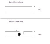
Attached is a drawing

The original + wire to the drive is now wired to one of the end connections of the pot. The middle connection of the pot is wired to the point on the drive where the PLC's + wire originally went. The - wire still goes to the drive AND it also goes to the other end connection of the pot.

If the speed does not move in the direction you want (typically increase with clockwise movement on the pot) the swap the connections to the outside terminals of the pot.

Pot.JPG
 
OkiePC

We did suggest that and evn using the panelview that is right there with the operator but the plant engineer nad production manager did not want to hear it.

This is one of those cases where I would do it my way, and get forgiveness later. You give the operator what you would want and have it working first, and make sure it works well, and can do more than the hardwired method. What are they going to do, complain because you went above and beyond with zero downtime? Make you put it back and do it their way?

Sometimes the boss needs to be proven to be wrong.

If they're that hardheaded, then at least don't make a divider, use the VFD trim input as RDS suggested.

The third terminal on the pot is just the other end of the resistor. The wiper bypasses part of the resistor making it adjustable. If you have a 10k ohm pot and measure the outer pins, you will read 10k ohms no matter where you put the wiper. The third pin often gets used when you find out that clockwise action of the knob needs to have an opposite effect on the signal...move the +vdc wire from pin 1 to pin 3, inverting the slope of the wiper signal.
 
Last edited:
Brucechase and bernie_carlton

Thank you very much for the drawing it really helps but I guess the only thing that is still cnfusing me from your drawings is why the - wire would even need to connect to terminal 3 of the pot at all and not just go straight to the analog input - of the drive without connecting to the pot? I am not questioning your circuit I just don't fully understand and I want to understand exactly what it will be doing and why it works that way.


OkiePC

Yes with these 2 guys they probably would make me redo it. The boss is just that much of an #&!hole. But it is a job.

Sorry if this is all simple stuff but I was a maintenance mechanic for many years and the most electrical I did was wire a 3 phase motor replacement chnage the occasional relay and and 2 wire limit switch. I was laid off from my job 2 years ago and now the company I am with requires yu to be good at mechanical,electrical and automation.

Thats ok though because I like to learn new things.

I don't think the minus wire needs to be connected to the pot, as long as the plus wire and the wiper are connected since you are just trimming that part of the circuit. Make sure you are trimming the signal wire and not its voltage reference.

This is still the wrong way to add a trim pot, when you can connect it to the drive as a 2nd analog input.

Don't apologize, this is not simple stuff when you are stuck doing things the 1978 method. I should apologize for thinking everyone should just buck up to their boss when he is wrong...just because I sometimes get away with it.
 
Last edited:

Similar Topics

Posted this to Reddit with little success, so I figured I would share it here as well. Very new to PLCs, but figured I would give it a shot to...
Replies
0
Views
111
Hello Folks, Has anyone configured a Momentum high speed counter on Unity 13.1. We need the wiring diagram for Momentum High speed counter and...
Replies
0
Views
73
Hey guys, the scenario is: I have already completed the drawing package for my system utilizing an A-B 440R-N23126 (Minotaur) safety relay. SoS...
Replies
0
Views
128
Maybe a stretch to call this a PLC question, but it does connect to a PLC input. I have two German switches: Sick WL9LG-3P2232 And a...
Replies
0
Views
106
Hello I wanted to ask some questions about the G120C drive and the protection for it. I want to control a pump, with the motor rating of 5.5 kW...
Replies
3
Views
193
Back
Top Bottom