OT Electronics Help

Brijm

Lifetime Supporting Member
Join Date
May 2006
Location
St. Marys, PA
Posts
645
I have a customer who burnt up a trace, and a capacitor on his pellet stove control board. They do not repair these boards, and a new one costs some $. I know a few here work with electronics, and thought someone might be able to give me an idea on what size capacitor to get. He knows the board may be damaged further, and would like to give it a shot to repair.

The Capacitor is connected to the fused incoming power and the outside leg of the transformer, and the second leg of the transformer. (I'm guessing the filter capacitor). I haven't done board work since school, so any help would be appreciated.

Thanks,
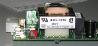
IMG_0662.JPG
 
If it is that little red round device to the left of the transformer, then it probably is a varistor. If it is connected to the fuse on a 120 volt circuit, then you probably need a varistor rated for 150 to 200 volts AC, and with a current rating greater than the fuse size. Either the existing varistor was sized a little too close to the voltage input, or there was a surge on the line (maybe lightning?).
 
Short term test, proceed at your own risk.
1. Cut the red varistor off the circuit board.
2. Repair burnt trace with simple point to point jumper, clearing any carbon tracking.
3. Temporarily replace fuse with 60 watt incandescent lamp (an ordinary light bulb), wired in series to simulate a fuse.
4. If available, use variable voltage transformer (Variac) to supply the power.
5. Energize the variac with output set on zero, slowly increase voltage, observing the light bulb. it should glow dim if at all if rest of board is OK. Full bright indicates something additional has failed and requires more troubleshooting. Possibly, the diode rectifiers or the little transformer has shorted.
6. If it is Urgent and if it tests OK, it can be put back in service temporarily until a new replacement varistor can be ordered. Otherwise, wait until the new part is installed before returning to service.
 
Last edited:
It's an MOV. It was blown by a line surge or thunderstorm. It's shorted now. Remove it. Check transformer primary to see if it's still intact. Schematic. You can run the unit for now with the MOV removed.
MOV From Mouser.
Replacement from NTE. Use a 1V130 or 2V130. I assume your line voltage is 120V. If it's 240, don't use these MOV's. Post and I'll find the correct replacement, or you can check specs here.
 
Wow, thanks to all for the assistance. I was pretty good at circuit board troubleshooting 10 years ago, but never did enough to work without a schematic.
Lightning or a surge sounds like the culprit. The pellet stove was shut down last spring, and he was just testing it now. Also, the trace coming from the fuse is blown.

You guys really go above and beyond
 
Last edited:
Lightning or a surge sounds like the culprit.
Lightning is a good suspect. It can sneak in where you would think it could not go. I once lived in an underground house, buried in a hill, 8" concrete walls, 10" thick concrete roof, with 24" of dirt on top and only the front wall exposed. One day my wife and the cat were in the bedroom when she heard a fizzing sound in the living room next to the wood stove. She and the cat both looked. There was a 6" diameter ball of fire (rare ball lightning) rolling around on the floor. The cat's hair was standing straight out due to the electric charge in the air.

We thought later that the lightning had found it's path from the roof down the metal stove pipe. You might want to warn your customer. He probably should consider adding a groudning system to his stove frame, with a heavy wire going to the nearest ground point. If he uses rods, I recommend a triangle of 3 rods, connected together with #6 wire.

That cat never was the same afterward. At the slightest sound of thunder, it would go hide unde the bed.
 
If he uses rods, I recommend a triangle of 3 rods, connected together with #6 wire.


Why a triangle of 3 rods? At what seperation distance?

I ask lancie because I have seen this before in the field years ago but never understood the purpose.

My gramps and all the other sparkies used to call it a delta ground setup. I don't know if thats correct terminology or just his.

Thanks
 
Why a triangle of 3 rods? At what seperation distance?

I ask lancie because I have seen this before in the field years ago but never understood the purpose.

My gramps and all the other sparkies used to call it a delta ground setup. I don't know if thats correct terminology or just his.

Thanks

The three ground rods are called a triad ground system. The separation is not a set number but determined by the soil type and its resistivity. They usually are further apart than the length of the rod.

This type of grounding seems to be going away. The last project I worked on had a perimeter ground with a ground well. This was done to get less than 10 ohms using the fall of potential method. The ground well was over 200 feet deep.


The 3 rods connected together act as 1 large rod. I've seen them at the main power entrance for the system ground and at remote builds due to lightning.

For some good ground reading, take a look at this link:
http://www.solacity.com/Docs/Erico%20-%20Practical%20Guide%20To%20Electrical%20Grounding.pdf
 
Yes, 3 rods are slightly better than one. However, ground rods are not very good in certain sandy soils. The best and cheapest grounding system that I have ever found is the Ufer system. I put a Ufer system in a plant at the Hawthorne Ammunition Plant in Hawthorne, Nevada in soil that was 100% dry desert sand, and got 2.5 ohms resistance from Ufer system to a test rod.
 
Hey Brian I see you are down in St. Marys. In Edinboro,PA not sure if you know where that is? There is a company actully its just one guy, all he does is repair circuit boards, power supplies and the like. He is really good and his prices are normally really good.He even does shipping for out of town customers. PM if you want his contact info.
 
Last edited:

Similar Topics

Dear All I have a delta electronic PLC communicating with Cimplicity SCADA through USB. Some virus attacked the PC and USB ports are nor working...
Replies
1
Views
2,505
Hi to all, I have to connect my rotery encoder to my plc inputs (incremental type), my question is: how can I extend the length of the...
Replies
12
Views
2,467
Hello, all! I'm on the cross-roads between applying for the: PE in Controls Systems - https://ncees.org/engineering/pe/control-systems/ and PE in...
Replies
7
Views
3,769
let's say I am developing my own PLC. I have schematics and I want to pass to PCB production. But I am new in electronics and I need to check my...
Replies
3
Views
1,858
Hi, Does anyone have any experience with hydraulic fluid static electricity affecting electronics?
Replies
2
Views
1,668
Back
Top Bottom