ML1400 Modbus Com Error to Powerflex 4M

DermotM

Lifetime Supporting Member
Join Date
Jun 2010
Location
Ireland
Posts
21
Hi All

My issue is with an MSG error code 37 - 'Message timed out in local processor' between an ML1400 and 8 Powerflex 4M's. When the VSD's are stopped the MSG functions work without error and as expected but when one or more of the drives are running some of the MSG's error. There is no pattern to which ones error and which do not, but generally more than 50% to 100% of the MSG's error on each cycle. Initially I suspected electrical noise on the 485 coms but now I'm not so sure The coms cable has been updated to Belden 9842 from standard screened cable and rerouted, but to no avail. The network setup is in line with AB manuals and good screening practice. Regardless of any changes in setup and layout the issue remains the same.

The 8 PF4m's are in a separate stainless steel panel to the plc and the power cables from the VSD's are routed directly from the drive panel to the motors without passing back through the plc panel.

Initial setup:
Start Source =5 Comms Port
Speed Ref = 5 Comms Port
Comms Data Rate = 4 (19.2 K, and is matched with my program configuration)
Node Address = 1 to 8 (Unique address)
Comms Format = 0 RTU 8 N -1

Because of unreliable stop commands as a result of the errors, run commands are now hard wired and the drive setup as follows

Start Source =2 - 2 wire
Speed Ref = 5 Comms Port
Comms Data Rate = 4 (19.2 K, and is matched with my program configuration)
Node Address = 1 to 8 (Unique address)
Comms Format = 0 RTU 8 N -1

Status MSG's are in a separate file to command MSG's

A bit frustrated so any suggestions appreciated
 
We do almost exactly the same setup except the command and status messages (one of each for each drive) are all in one file. It cycles through all the messages, one at a time then starts over. We cease all messaging when power is turned off to the drives, naturally, and begin again when it is re-applied. A complete sequence through all the drives takes place 4-5 times per second. Just like you we use hard contacts for the run command.
 
Thanks for your comments Bernie, do you have any thoughts on the cause of the error, when a message rung goes true the associated msg either works and switches the dn bit within approx 0.25 sec whereas when a particular node is problematic it remains enabled for approx 10-15sec before switching the error bit.

I have a small number of projects running using EthernetIp, RS232 and RS485 messaging but have not experienced this problem before.
 
The timeout error is when the Micrologix receives nothing intelligible back, not even a Modbus error message. I don't trust the 'buffering' that the the system is supposedly capable of. Ethernet messages are inherently numbered and can be sent and received back in weird order and re-assembled. Modbus messages to not have an incrementing 'message number'. Try changing to an all in one messaging, not a separate file. Make sure that only one message at a time can be active.

Other than that, maybe the grounding of the 485 cable is at issue and only shows up with the ON state of the drives. The shield for the cable from the Micrologix to the first drive is terminated only at the Micrologix end. Each continuing cable's shield is grounded only at the earlier drive. Make sure to use the proper terminating resistor at each of the physical ends of the cable. Preserve pure daisy chain, no 'T's.
 
We're on the same track! the way you describe the grounding and shielding is the way I have it. the shield on the cable from the NC01 to node 1 pf4m is connected only at the nc01 and the shield on the cable from node1 to node2 pf is connected to t16 with a ground cable also connected from the terminal to the main ground (not the ground terminal on the pf heatsink), this continues to node 8 where I'm using the AK-U0-RJ45-SC1 splitter and termination resistor AK-U0-RJ45-TR1. The NC01 end has a standard 120R resistor (tested) across A&B

I will try all com msg's in one file, although the present setup only allows one message chain to operate at a time.

Again thank you for your thoughts
 
P.s just to clarify, the shield from node 1 to node 2 is connected ONLY at n1 and from n2 to n3 only at n2 and so on
 
Your problem is almost certainly RS-485 noise.

I've always been confused by RA's documentation for how the DSI port works on PowerFlex 4-series drives, but with it's understandable if you sort it out from first principles.

First, understand that RS-485 requires THREE wires; Data A and Data B must have a common reference voltage.

Good isolated RS-485 systems provide that third wire. A-B's own legacy Data Highway 485 has a dedicated common wire.

When the vendor hasn't provided for a third wire, you have two choices: use the cable shield as a return wire, or use Ground.

The PowerFlex 4-series uses GROUND as a "return wire" for the RS-485 network connection.

The MicroLogix 1100 and 1400 also use GROUND as a "return wire" for the RS-485 connection. Unlike the SLC-500 and MicroLogix 1000/1200/1500 that use the isolated Common on the 1761-NET-AIC module, the MicroLogix 1100 and 1400 have a non-isolated RS-485 port.

The Protective Earth for the drives absolutely needs to have the same ground potential as the Protective Earth used for the MicroLogix.

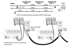
There's a pretty good diagram in the PowerFlex 4M User Manual, on page C-1, that shows the shield on the two-conductor "DSI" cable being used as an ordinary continuous shield.

As described in that diagram, the cable shield should be connected to ground in only one place. In this system, I would make that shield grounding point the first drive's PE terminal, not the MicroLogix cabinet or the 1763-NC01.

In my humble opinion this diagram is confusing, because the top schematic shows the cable shield being connected at the "Modbus RTU master" end only, but the terminal connection diagram below illustrates the connection of the cable shield both to T16 and to PE at the first PowerFlex 4M drive. If the cable shield is grounded at the Modbus RTU Master end, then that's two connections to Ground, which you don't want.

Additional confusion comes from RA's description of Terminal 16 as the "DSI Shield" and recommending or requiring the connection of Terminal 16 (on the 4M) or Terminal 19 (on the 40) to Protective Earth. What they mean by "DSI Shield" is that T16 (or T19) is connected to the metal shell of the DSI plug. This connection is, as far as I can tell, not required to connect the RS-485 common reference to PE.

What this diagram doesn't show is your "segmented shield" implementation. I don't think this provides as good noise reduction as a continuous shield.

To summarize:

1. Use a continuous shield, connected to PE at one point only.
2. Make sure both the PLC cabinet and the Drives cabinet share the same ground potential.

FigureC1.png
 
I have checked ground between both panels and all looks good physically and potentially. Three different grounding and screening combinations have been tried but each used either the shield and/or ground terminals on the 1763-NC01 and produced exactly the same result as described above.

I'll let you know how I get on. Many thanks for your clarity
 
Are you re-cycling the communication string [B3:8/0] at the end of your subroutine, or are you simply restarting the poll after every 1 sec?

If you are, then what is preventing T4:14 from interupting the communication cycle mid stream?

If not, how can you guarantee that your 1 sec rate is long enough if you experience a comm error and it goes into a timeout period?

Without being able to see the rest of your code, I appears that if you get one comm error it would quickly escalate into a series of errors.

It is never a bad Idea to use the ST bit of the message instruction to interlock comm calls.

Not knowing what triggers your logic in network 0, there also seems to be the risk of the T4:14 timer getting re-triggered when it isn't supposed to be. Possibly that might explain the difference between when drives are running and when they are not.

All that being said, I'm still with Ken and Bernie about it probably being a noise issue. I'll never understand why they didn't add the common right at the RJ45 connector so that you can chain these things without all kinds of goofy jumper wires.
 
Dermot,

Do you have term 4 of the PF4M connected to GND? If so, remove it and see what the result is...

Regards,

Rob
 
In the attached printout there are 16 MSG functions in total, 8 for command status and 8 for reference feedback. When T4:14 sets the DN bit it latches B3:8/0 which enables MG14:0 through the ONS, so as a result of B3:8/0 latching in combination with the ONS [B17:2/2] any further set and reset of T4:14 DN bit is ignored until B3:8/0 is unlatched.

When a MSG sets either the DN or ER bit this then in turn enables the next MSG in the chain. The setting of the DN or ER bit on the last MSG in the chain unlatches B3:8/0 ready for the next cycle enable through T4:14/DN.

Rob, yes I do have T4 connected to ground so will try your suggestion.

Again many thanks for all of your feedback

Dermot
 
I have run into phantom comms issues on serial many times. Not being an electrical engineer, I could never find (or understand!) root cause. Anyway, I always attribute it too noise - what makes this a strong hypothesis here, as others have said, is that it works fine with the drives off. My solution has been to use opto isolators on the serial ports. See http://www.bb-elec.com/product_family.asp?familyid=12.

I don't know if it would help you here, but I always have a couple lying around the shop so I would wire it in and see if it helps. If not... really only lose a couple of man-hours for the test.
 

Similar Topics

If I set up a ML1400 as a Modbus RTU slave, and click the extended files tickbox, then set up my files with 200 elements, will the Modbus...
Replies
1
Views
1,073
I need to do 5 reads and 1 write on 2 devices. So that is 10 and 2 total. It seems I can't use indirect addressing with MG registers, which is...
Replies
11
Views
3,121
I have a device that I am communicating with here that is using Modbus to store values from a gas analyzer and I want to transfer these to a PLC...
Replies
9
Views
3,759
I am currently working on a project with an Epson Scara robot using an RC-90 controller communicating with a ML1400 Ser. B PLC. The robot...
Replies
4
Views
3,991
I have an Allen-Bradley MicroLogix 1400, and have been working with it for a few months now and understand its basics pretty well. Up to now I've...
Replies
4
Views
3,948
Back
Top Bottom