pid rslogix5000

Join Date
May 2006
Location
huddersfield
Posts
67
Hi i am trying to use the pid block in my rslogix 5000 project,i have set the block up and set a tag (pid type0 i have also scaled and entered the relative pv an cv.I am using a 4-2ma simulator to adjust the pv value and can see it altering in the pid block,the problem is my pid output remains at 0% no matter what i do?? sure i am missing something simple has anybody got any ideas??
alex
 
as you said, it's probably just something simple - but there are a LOT of simple things that it could be ...

best GUESS so far: are you sure that the PID rung is being scanned? ...

post your code ... you'll have to zip the ACD file before you post it - forum rule ...
 
Alex, you have not said that you have set the P, I, and D terms.

With a P term of zero, there will be no output from the PID block.
 
short on time ... this will have to be brief ...

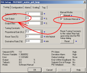
first of all, do you realize that in the version you posted - you have your PID set for Software Manual mode? ... with that particular setting your output will be the value you have entered at Set Output - which in the version you posted happens to be 0.0% ... in other words, you've "manually" told it to give you an output of ZERO - and (bless its little heart) that's exactly what it's doing ...

going further ... what is your scaling set up to represent? ... specifically, where did you get the numbers 17407.0 and 2.5 for your Process Variable? ...

just a tip: you can delete that RES after the PID - the "free wheeling timer" setup on the previous rung will automatically take care of the reset action for you ...

and I'm forced to wonder: how is your TON timer showing its DONE bit as ON - when the Accumulator is only 500 - and the Preset is 1000? ... were you tinkering around with an offline program before you posted it? ... if so, that's not a good idea ... we need to see your system as close to "running conditions" as possible to be able to help you with detailed answers ... if you need more help, just "save" the program from the running machine - and post a copy of that file (warts and all) ...

incidentally, I did plug your PID setup into one of my lab processors - and it DID give an output - once the PV fell below the SP ...

AND - (of course) ...

after I took it out of the Software Manual mode ...

hope this helps ... wish I had more time to play ...

.
sw_manual.PNG
 
Last edited:
Thanks Ron it was as simple as unchecking that box.I appreciate your help.Whilst playing around with the pid block i had a idea of using a few of them just to scale( as there is no scp) some ai reading temp to the actual values is this a bad idea? by the way i got the figure you mentioned by inputting 20ma and monitoring the value (although think my batterys going on the simulator)
Alex
 
Thanks Ron it was as simple as unchecking that box.

well, sometimes it really IS something simple – it's just that where PID is concerned there is so much "simple" stuff floating around that it's often difficult to find the appropriate simple thing to change ...

yet another example of why it's better to post your program rather than asking the forum to make random guesses ...

I appreciate your help.

you're quite welcome ...

Whilst playing around with the pid block i had a idea of using a few of them just to scale ... is this a bad idea?

well, technically it COULD work – but it would be somewhat akin to using a 10-pound sledgehammer to swat a mosquito ... let's just say that other programmers would tend to "look at you askance" – and we'll let it go at that ...

in most cases, a well-crafted CPT statement would be much more appropriate for scaling your signals ...

by the way i got the figure you mentioned by inputting 20ma and monitoring the value


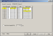
well, something there definitely needs to be investigated ... with the "Scaled for PID" settings that you're using for Channel 0 on your analog input module, a 20 mA signal SHOULD give you a signal of only 16383 ...

here's just a wild guess ... is it possible that you "tested" by connecting your signal generator to one of your "unused" channels – rather than to the actual Channel 0 that you've specified for your PID's input signal? ...

the reason that I'm asking is that most of your other channels are set up for "Raw/Proportional" scaling ... and such a setting SHOULD give you a reading of 6241 at 4 mA ... and a reading of 31206 at 20 mA ... that sort of range COULD be consistent with the 17407 reading that you've reported – IF (big IF) your weak battery only allowed the signal to go up as high as 11.16 mA while on the 20 mA setting ...

yes, that's a LOT of pure speculation – but SOMETHING fishy is going on with the scaling number that you reported ... you should investigate that situation fully BEFORE you go too far with your PID loop tuning ...

secret handshake: changing the scaling often has an effect on the tuning ... in simplest terms, if you tune the PID first - and THEN fix the scaling - then you might have to start tuning the loop all over again from scratch ...

anyway – time's up – I've got to get back to work ...

glad I was able to help ... good luck with your project ...

.

scaling_pid_vs_proportional.PNG
 
Last edited:

Similar Topics

Hello, I have a program that monitors pressure in a manifold discharge pipe. Pressure in the pipe should be less then 7.5 PSI. If the pressure is...
Replies
17
Views
12,751
Hello all, I cant figure out why my PID is oscillating between 0 and 100 percent. My set point is steady and whenever I take my PID out of...
Replies
4
Views
3,472
Hello, Question: (Temp is whats being controlled here by 3 fans) Using a PID; can I set my output (CV) to be 100% at a specific input (PV)? In...
Replies
9
Views
2,232
Hello, I have already searched for that in the forum but did not get any satisfying answer, so here it goes: I have a 1769-L36ERM that controls...
Replies
4
Views
3,112
Dear all I would like to ask you for help in solving one algorithm, because I never worked with cascade PID. I have to realize heating valve...
Replies
12
Views
8,319
Back
Top Bottom