PLC 5 BTR & BTW questions

iraiam

Member
Join Date
Jul 2011
Location
Right here
Posts
146
I set up an analog card (1771-IFE/A) in differential mode, this gave me 8 functional analog inputs. I used the RSLogix generated rungs with a BTW word length of 37 and a BTR word length of 20.

At work I see numerous analog modules with BTR & BTW that have a completely different word length, only a couple of these analog inputs are used on the module, the rest are shorted to module common.

I have been unable to understand the relationship between word length and the number of active inputs on the module as of yet, (if there is one):unsure:

Here is a simple ladder to help, all 8 differential inputs work, I only scaled one so far.

Any understanding you can give me would be much appreciated


IGOR-page-001.jpg
 
The BTW configures the module.
There may be up 16 channels, a min & max scale value is required for each channel. This is a total of 32 words. Next there 5 other configuration words which set up data type, single ended or differential plus the sign of the scale values.

The BTR readers the data, so there are 16 words for the channel values. Plus 5 words for general status - over / underflow sign etc.

If you are not using all channels you can reduce the BTW length by 2 words for each channel not used and the BTR length by 1.

This is all from memory, so it might be safer to read the manual!
 
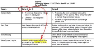
see the chart on page 4-8 of the following manual:

http://literature.rockwellautomation.com/idc/groups/literature/documents/um/1771-um663_-en-p.pdf

this shows the length for the newer 1771-IFE/C model – the manual for the older 1771-IFE/A and 1771-IFE/B modules are no longer on the website ...

the length shown (39 words) includes two "extra" words at the end used for calibrating the newer "C" modules ... the length that you need for the "A" module that you're working with is 37 words – it doesn't support the calibration feature ...

you can find that specification for 37 words in the chart on page B-1 at the back of the manual ...

tip: most programmers just go ahead and transfer the maximum number of words – even though some of those words aren't really needed ...

going further: I'd post your complete RSP file if I were you ... the numbers in your CPT instruction make it APPPEAR that your module setup isn't exactly "optimized" ... (note that you'll have to zip the RSP file before you post it – forum rule) ...

.

btw_length.jpg
 
Last edited:
I agree with Mike the manual has a good breakdown of the block transfer data. I did a lot of reverse engineering PLC5 programs at a process plant a couple of years ago. There are about 5 pages I printed out of every manual thy where the BTR BTW layouts. Look at the N13 data file and change the radix to BCD see it those numbers make since to you now. Some specialty cards broke the BCD number in to 2 so you might need a calculator that does BCD. Be careful of windows calculator it will cut off leading zeros
 
Thanks for the information,

I do have a hard copy manual for the 1771-IFE/C module I'll read it again.

Ron, I haven't done any optimization at all, I left the stock raw min (0) and max (4095) values alone and just scaled the input with y=mx+b. In the N13 data file the input reads from min (0) to max (16533)decimal, These are the numbers I used in the slope intercept formula, I'm not sure if it's right but it had the desired output.

It's not much of a program, just experimentation, but here it is.
 
Last edited:
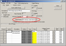
change this setting to Two's Complement Binary and see if your life gets easier ... your data SHOULD be coming out 0 to 4095 ... the weird numbers that you're actually seeing are the result of this improper setting ...

BCD is the "default" setting for the old PLC-2 processors ...

It's not much of a program, just experimentation, but here it is.

it's an EXCELLENT program for teaching yourself - and "experimentation" is the best way to learn ... party on ...

.

BCD_2SCOMP.PNG
 
Last edited:
change this setting to Two's Complement Binary and see if your life gets easier ... your data SHOULD be coming out 0 to 4095 ... the weird numbers that you're actually seeing are the result of this improper setting ...

BCD is the "default" setting for the old PLC-2 processors ...


it's an EXCELLENT program for teaching yourself - and "experimentation" is the best way to learn ... party on ...

.

Thanks for the tip, I changed it and then changed the scaling computation.

I have seen this same improper setting at work, it's about a 35 year old plant so it is very possible that some of the PLC-5 processors were upgraded from an earlier model.
 
I have seen this same improper setting at work, it's about a 35 year old plant so it is very possible that some of the PLC-5 processors were upgraded from an earlier model.

never argue with success (in other words, if it ain't broke – don't fix it) ...

even if the numbers can be made to work out with the BCD setting – you're setting the "max" scaling to 4095 ... eventually someone will come along and ask: "where is the value 16533 coming from?" ... apparently in your case it's been about 35 years and nobody's gotten excited about it yet ...

I agree, it would be a lot of work just to have the same result, one of them is an L80/E processor with lots of computations based on lots of analog, and the 100K memory nearly full. If I look through that code for too long my right eye starts to twitch uncontrollably:oops:. Sounds like work for someone with an engineers pay rate to me.
 

Similar Topics

I have an application that is duplicated on a similar production line. A 1794-IE8 Flex I/O module is installed and connected to 4 pressure...
Replies
2
Views
2,437
Hello, I'm new here and looking for some help from you all. I'm writing BTR and BTW instructions in RSLogix 500 for a 1794-IE8 card with...
Replies
1
Views
7,264
The present system:- Consists of a PLC-5/40 E CPU mounted in a 8-slot chassis. There are several remote I/O panels consisting of five 16 slot...
Replies
43
Views
30,075
Hello, I am trying to create a network status map at a plant. I'm assuming the comm status bit of dnet nodes is in the BTR/BTW instruction that...
Replies
0
Views
974
Hello all, I am adding a 1771 VHSC card to an existing system in order to more precisely control part positioning. The problem I am having right...
Replies
2
Views
2,797
Back
Top Bottom