blackcobra
Member
Hello , My name is Gavin an I am new both your forum and the field of PLC programing, an hence I was wondering if I could get a bit of help from some of the seasoned vets. I am a software engineer by profession so I am used to a slightly different style of programing Ok here's my problem-
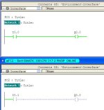
I am designing a program using a ladder diagram, the whole thing is fairly simple as the PLC has to control a pneumatic arm for some automation type of application. The Machine has an automatic and manual switch which is connected to I1.0 of the PLC. When the Machine is placed into manual mode the I1.O input goes high hence this input has been used to differentiate between the two modes. My automation cycle is happening without A Jazz however in manual mode which is much simpler than automation mode the PLC just refuses to turn on outputs Q0.2 AN Q0.4 which are basically the only things required of it in this mode The only contact that does work in this mode is Q1.0 the funny thing is that the program status in Step 7 shows all these contacts as turned on but the PLC refuses to light up the LEDs corresponding to Q0.2 AN Q0.4, and since the auto manual switch is being checked as a contact there is no power going to the auto cycle. However if the manual mode program is run separately the whole thing works flawlessly ! ! !
Coming form a software programing back ground i was just wondering if there were some quirks about this system i have overlooked.
Thanks for all the time you took to read through my problem any assistance you can render will be greatly appreciated.
Regards,
Gavin
Last edited:


