PID in RsLogix 5000

Join Date
Jun 2010
Location
VT
Posts
8
Hi all,

I am trying to use several different PID loops in a program that I have converted from SLC500 logic. I started to troubleshoot the first loop, and I cannot seem to get any output %. I definately do not have it set to manual mode, and to me, at least, the parameters look OK. At first, it was no set to "trigger", that is, I was running it every scan of the continuous program. I have changed that, to no effect.

I have spent 2 days pouring through all the information I could find, and I am still stuck, can anyone here help?

The PID instruction is on Rung 22 of the routine "Bottom Steering". I would greatly appreciate any ideas.

Also, I don't know if it is related or not, but I cannot turn off the PID's ".ini" bit. In all of the sample code I looked at, this bit was off. As I said, I don't know if that means anything or not.

Thanks!

Unfortunately, the file was too big to attach here, but you should be able to download it from this link:

https://docs.google.com/open?id=0BwPH-XeBrBcHMDlkZjI0ODMtMDIyYi00ZjY0LThmM2QtNzlmMzY5MmI2NGVl
 
Your PID is set for reverse acting (SP-PV). With the process variable above the setpoint, the output will not increase. Have you tried raising the setpoint above the PV?

In the SLC500 the PID instruction does not need conditions preceeding it on the rung and updates at the loop update time. For ControlLogix, the PID should be triggered at the loop update rate. It's better to put it in a periodic task with the loop update time set to the task rate. Or better yet, use a PIDE instruction in a function block routine.

Also, the Logix PID does not require 0-16383 scaling and can be scaled to engineering units in the instruction itself. You could scale in the PID and not use the SCP instructions.
 
Thanks for the help, I noticed the reverse action after I wrote this - believe me, that was a "slap my forehead" moment.

The scaling is all done the way it is because it was converted from a SLC PID, and I didn't want to change too much at once until I worked with it more.

I had just found out about the periodic trigger not long before I created this post. I am currently working on putting all of the PIDs into periodic tasks, thanks. Everything I read says that I need to, but I still don't quite get why. Why is it diffrent from the SLC PID instructions?.. It doesn't make sense that you need to bother with an update time, if you're only allowing the rung to execute at that update time (but I will still do it, of course!)
Thanks for the help!
 
I had just found out about the periodic trigger not long before I created this post. I am currently working on putting all of the PIDs into periodic tasks (1), thanks. Everything I read says that I need to, but I still don't quite get why. Why is it diffrent from the SLC PID instructions?.. It doesn't make sense that you need to bother with an update time (2), if you're only allowing the rung to execute at that update time (but I will still do it, of course!)

(1) You only need to put the PID instructions themselves into the periodic task - leave all of the "glue-logic", mode-switching, setpoint changing etc. in the continuous task. That way you will only need 1 periodic task for all your PIDs.

If you have a lot of PIDs, it is a good idea to "spread the load" so they don't all execute every time the periodic task is triggered. You can do this by using a "scan-count", for example, and each trigger of the periodic task executes a smaller number of PIDs based on the scan count value.

Remember to set the Update of the PID tags (.UPD) to the actual period the PIDs are scanned, so if you have divided them up as above remember to take account of the multiplexing.

(2) The Update time you set into the PID is used in the calculations - PID control is a time-based algorithm, so the maths needs to know how long has elapsed since it last executed, in order to determine the corrective action required. And yes, it does seem kinda overkill that you've got to set .UPD and ensure the PID is scanned at that rate. You would think that the PID could measure how long has elapsed since last execution, but it hasn't been programmed that way.

If you want to, you can read the periodic task rate using GSV, (adjust for multiplexing if used), and fire that into the .UPD of the PID tags. That will automatically take into account any tinkering with the periodic task that may occur in the future. I usually do this as a matter of course, safe in the knowledge that my carefully tuned PIDs stay that way.
 
I am new to RS5000 and have a question. I too tried to make the PID in the regular program file. It was acting extremly funny. So I read this, figured out how to make a Periodic Task file. Labeled it PID, with 1 file in it. Directly cut and pasted my PID rung to this Periodic PID ladder file. Everything worked well. So I deleted the PID form the continious Ladder file and it stopped working. Seems I have to have the same instruction in both the continious and Periodic files? Is this normal? Changing the PID data in either of the ladder programs changes it on both. Just confused. I'm a PLC/SLC guy. Learning CLX by theseat of my pants


(1) You only need to put the PID instructions themselves into the periodic task - leave all of the "glue-logic", mode-switching, setpoint changing etc. in the continuous task. That way you will only need 1 periodic task for all your PIDs.

If you have a lot of PIDs, it is a good idea to "spread the load" so they don't all execute every time the periodic task is triggered. You can do this by using a "scan-count", for example, and each trigger of the periodic task executes a smaller number of PIDs based on the scan count value.

Remember to set the Update of the PID tags (.UPD) to the actual period the PIDs are scanned, so if you have divided them up as above remember to take account of the multiplexing.

(2) The Update time you set into the PID is used in the calculations - PID control is a time-based algorithm, so the maths needs to know how long has elapsed since it last executed, in order to determine the corrective action required. And yes, it does seem kinda overkill that you've got to set .UPD and ensure the PID is scanned at that rate. You would think that the PID could measure how long has elapsed since last execution, but it hasn't been programmed that way.

If you want to, you can read the periodic task rate using GSV, (adjust for multiplexing if used), and fire that into the .UPD of the PID tags. That will automatically take into account any tinkering with the periodic task that may occur in the future. I usually do this as a matter of course, safe in the knowledge that my carefully tuned PIDs stay that way.
 
You absolutely do not have to have the PID instruction in both the Continuous task, and the Periodic Task. Just once, and once only, or the PID maths will get screwed.

edit: irrelevant stuff removed.
 
Last edited:
You absolutely do not have to have the PID instruction in both the Continuous task, and the Periodic Task. Just once, and once only, or the PID maths will get screwed.

edit: irrelevant stuff removed.

Well I only have controller tags in the program. No Program tags used. I copied the PID instruction with tags directly from the Main program and pasted into the Periodic ladder file. Tested it 3x. Delete the PID from the Main program and it doesnt work, the PID just freezes up. Have in both Main and periodic, Works great. Have just in the Main and math is all messed up
 
Last edited:
Well I only have controller tags in the program. No Program tags used. I copied the PID instruction with tags directly from the Main program and pasted into the Periodic ladder file. Tested it 3x. Delete the PID from the Main program and it doesnt work. Have in both Main and periodic, Works great. Have just in the Main and math is all messed up

Can you post a link to the new code, and I will take a look at that...
 
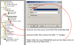
see if this helps ...

secret handshake:

when you create a new PROGRAM, none of the ROUTINES in that new program will be scanned/executed by the processor unless one of the ROUTINES is set up as the "Main" ROUTINE ... the "Main" ROUTINE gets a "1" badge - and then you typically use a JSR instruction to "jump to other subroutines" within the PROGRAM to get the processor to scan them too ...

.

number_1_badge.PNG
 
Last edited:

Similar Topics

Hi, Long time not in the forum, and not in the programming. I´m getting back. I was issued a conversion from RSLogix 500 to RSLogix 5000 (studio...
Replies
0
Views
1,288
So I have a PID loop on an 1756-L61 running V17 software just for background. Also the PID PV is a pressure transmitter and the CV is speed sent...
Replies
1
Views
894
Hi All, I have a PID control application that I would like to get your opinions on. As I am reality new to PID loops I am struggling somewhat...
Replies
14
Views
4,276
Hi, I am confuse with the scaling tab on the PID dialog box. On the Process variable I am using a tag that is already scale. 0 to 16 Feet Level...
Replies
2
Views
2,417
Hi I am trying to understand the best method of providing bumpless transfer to the PID function (not PIDE) The existing code shows In Manual...
Replies
10
Views
4,612
Back
Top Bottom