Ladder software timer problem help!!!!

ALIMARY15

Member
Join Date
Jul 2011
Location
italy
Posts
75
Good morning to everyone i would like to ask for some help!

I have created a software for the automation of a milling machine! Its a school project where we have to control the position of the mill axis. I am using a Plc DL05 with a C-more micro panel.
I have created the software for the position control of the axes using the Quadrature Encoder Mode 40 of the plc manual as I am using a quadrature encoder for controlling the position. the counter i am using its the ct76 counter.
In particular my PLC has to control 3 output variables : Y0 , the motor power on and off, Y1, command for the relays to invert the direction of the motor, and Y2 which is a command that will attach,detach a magnetic friction that is between the motor and the axis (in the case the operator want to move the mill axes manually).

My software seems to work well except for a little thing i would like to ask help! In my application i would like to use some time delay between the time my motor is powered on and the friction is attached, as well between the time my motor is powered off and the friction is detached.

So i would like something like this: when Y0 is SET , there is like 5 secods delay then the Y2 is SET,
and viceversa when i want to stop everything, i RST the Y2 and then after some seconds i RST the Y0.
How this can be done?

I have tried to use TMR boxes but this seems to affect the counters and so the quadrature counting won't work well. Has anyone some ideas or advice for me??

I attach you here my software : the "milling.zip" its my original software that works except from the fact that the Y0 and Y2 outputs will be turning on and off together!
the second attachment ("timers") its my trial to use timers for obtaining a delay . I don't understand what is wrong and why i cannot obtain the delay between the two outputs!

please can anyone help me? thank you so much!
 
So i would like something like this: when Y0 is SET , there is like 5 seconds delay, then the Y2 is SET, and viceversa: when i want to stop everything, I RST the Y2 and then after some seconds I RST the Y0.
How this can be done?
I am not sure, but in Subroutines K2 and K4, you first Set Y2, then after 5 seconds you set Y0. It seems that this is reversed from what you want.

Also, I see two logic places where you turn the motor output Y0 to ON, and two other places where you turn it OFF. Generally, it is best to have only 1 place where a motor is switched ON and OFF. This keeps things safer, and much easier to troubleshoot.

A timer inside a subroutine can be a problem, because it only runs when the subroutine is active. For example, in Subroutine K2, this is the logic sequence:
1. Y2 and C15 are SET;
2. Timer T0 starts;
3. Rung 18 causes an immediate RETURN to the Rung 6 of the main program (without waiting for T0 to even reach 0.01 seconds)!

To make Subroutine K2 wait until Timer T0 reaches 5 seconds, you would have to put an instruction on Rung 18 to wait until ALL actions are complete. This maybe could be when C11 goes on, or when the counter is done.

Question: How are you going to RESET this counter, when it is only enabled when Subroutine K2 is active?

EDIT: For others who want to help but do not have the DirectSoft software, here is a PDF file of Mary's second program.
 
Last edited:
I am not sure, but in Subroutines K2 and K4, you first Set Y2, then after 5 seconds you set Y0. It seems that this is reversed from what you want.

Also, I see two logic places where you turn the motor output Y0 to ON, and two other places where you turn it OFF. Generally, it is best to have only 1 place where a motor is switched ON and OFF. This keeps things safer, and much easier to troubleshoot.

A timer inside a subroutine can be a problem, because it only runs when the subroutine is active. For example, in Subroutine K2, this is the logic sequence:
1. Y2 and C15 are SET;
2. Timer T0 starts;
3. Rung 18 causes an immediate RETURN to the Rung 6 of the main program (without waiting for T0 to even reach 0.01 seconds)!

To make Subroutine K2 wait until Timer T0 reaches 5 seconds, you would have to put an instruction on Rung 18 to wait until ALL actions are complete. This maybe could be when C11 goes on, or when the counter is done.

Question: How are you going to RESET this counter, when it is only enabled when Subroutine K2 is active?

EDIT: For others who want to help but do not have the DirectSoft software, here is a PDF file of Mary's second program.
Thank you for your reply! The counter is reset by the C20 variable. I reset the counter when i reach the limit the operator wanted or when the stop button is pressed or if i reach the physical end of the axis.

I chose to make two subroutines K2 and K3 to indicate the right or left movement of the axis as the two subroutines are accessible when the operator push some buttons from the chore panel.
I know the timers are creating me troubles into the subroutines so i can i do to make this delay between Y0 and Y2? I want to make this time delay because i fear that from a mechanical point of view attaching the friction at the same time the motor is powered on would be a disaster!

How should i change my rungs?

thank you
 
The counter is reset by the C20 variable. I reset the counter when i reach the limit the operator wanted or when the stop button is pressed or if i reach the physical end of the axis.
Yes, but my question is: how will the counter work when it is ony enabled when the subroutine is active? It cannot count all the time, only some of the time. A counter that misses many counts is not a very good counter. Most simple fix: move the counter to the main program. If you leave it in a subroutine, then you must make sure that the subroutine is called on EVERY PLC scan loop.

How should i change my rungs?
One sure certain way is to remove all subroutines and put all rungs into the main program.

You see, the problem with the timers is that they WILL NOT ever reach 5 seconds, because each Subroutine K2 and K4 only will be active for ONE scan of your PLC. If you put a timer in a Subroutine: (1)you must be prepared to halt the subroutine long enough for the timer to reach its preset value, or you must make sure that the subroutine is called EVERY scan until the timer is done, OR. (2)you can delay the subroutine RETURN by making it conditional (it only does the RETURN after some contact closes).

Reminder of how a subroutine call works: (1) your main program jumps to the subroutine first rung, (2) the subroutine is scanned one rung at a time and each instruction is done, (3) when a RETURN is seen, the logic control is returned to the next rung of the main program, (4) if a timer was started in the subroutine, but the subroutine is only scanned ONE time, then the timer never reaches its set value.

Simple fix: Delete the subroutines!

I want to make this time delay because i fear that from a mechanical point of view attaching the friction at the same time the motor is powered on would be a disaster!
Yes, I seriously want to prevent a disaster. What is a "friction"? That term does not translate well to English. Is this a type of magnetic coupler or clutch, which connects the motor to the milling machine gear?
 
Last edited:
Alimary,

You have used SET and RST many times, where a simple OUT coil would have been better, safer, and would have required many fewer instructions. When turning a motor on and off, using SET and RST is not a very smart practice. The difference is that OUT is only ON when the rung logic preceding is ON. A SET can lock a motor ON, then if something goes wrong (your PLC is struck by lightning), there may be no way to shut the motor off.

Question: Are C6, C7, and C10 momentary-contact pushbuttons, or maintained-contact switches? If they are momentary and only on for a short time, then your Subroutines cannot work correctly as they are written, because they will only be called 1 time (or for a few times while the buttons are on, not long enough for your 5-second timers to work.

On the other hand, if C6 and C7 are maintained-contact switches, then on Rung 5, you are setting CTA76 to 0 many times, on each loop of the PLC scan.

If C7 and C7 are maintained-contact, then for both Left and Right Motion, it seems that, once the desired position is reached, there is nothing that locks out the C6, C7, and C10 control buttons. The PLC will continue to try to turn on the motor, engage the magnetic coupling, and enable the counters even when the set position has been reached. You need some logic to disable the buttons and the Subroutines as long as Current Real Position = Desired Set Position.

Rung 5: The LDD K0 appears to set the CTA76 counter to 0, which is logical if it is done 1 time at the beginning of the Motion to Right. However, I think it will be done MANY times, on each scan of the PLC while C6 and C10 are turned on. You should use a PD one-shot bit to only do the CTA76 set to 0 one time when C6 goes to ON.

Suggestion: Set C6 and C7 to be pushbuttons that must be held down to cause the motor to run (using an OUT coil for Y0). Then add a PD one-shot to Rung 5 to reset CTA76 to 0 only 1 time for each press of C6.

I have tried to use TMR boxes but this seems to affect the counters and so the quadrature counting won't work well.
The use of any timer SHOULD NOT have any effect on the quadrature counter, or on any other counter. The problem is somewhere else, probably caused by the way you have used the pushbuttons and the subroutines.
 
Last edited:
Alimary,

You have used SET and RST many times, where a simple OUT coil would have been better, safer, and would have required many fewer instructions. When turning a motor on and off, using SET and RST is not a very smart practice. The difference is that OUT is only ON when the rung logic preceding is ON. A SET can lock a motor ON, then if something goes wrong (your PLC is struck by lightning), there may be no way to shut the motor off.

Question: Are C6, C7, and C10 momentary-contact pushbuttons, or maintained-contact switches? If they are momentary and only on for a short time, then your Subroutines cannot work correctly as they are written, because they will only be called 1 time (or for a few times while the buttons are on, not long enough for your 5-second timers to work.

On the other hand, if C6 and C7 are maintained-contact switches, then on Rung 5, you are setting CTA76 to 0 many times, on each loop of the PLC scan.

If C7 and C7 are maintained-contact, then for both Left and Right Motion, it seems that, once the desired position is reached, there is nothing that locks out the C6, C7, and C10 control buttons. The PLC will continue to try to turn on the motor, engage the magnetic coupling, and enable the counters even when the set position has been reached. You need some logic to disable the buttons and the Subroutines as long as Current Real Position = Desired Set Position.

Rung 5: The LDD K0 appears to set the CTA76 counter to 0, which is logical if it is done 1 time at the beginning of the Motion to Right. However, I think it will be done MANY times, on each scan of the PLC while C6 and C10 are turned on. You should use a PD one-shot bit to only do the CTA76 set to 0 one time when C6 goes to ON.

Suggestion: Set C6 and C7 to be pushbuttons that must be held down to cause the motor to run (using an OUT coil for Y0). Then add a PD one-shot to Rung 5 to reset CTA76 to 0 only 1 time for each press of C6.

The use of any timer SHOULD NOT have any effect on the quadrature counter, or on any other counter. The problem is somewhere else, probably caused by the way you have used the pushbuttons and the subroutines.


Thank you please can you correct my software and maybe type me the instructions i have to insert ?

Im getting crazy in debugging and i need to present this project in this week
 
Alimary,


Rung 5: The LDD K0 appears to set the CTA76 counter to 0, which is logical if it is done 1 time at the beginning of the Motion to Right. However, I think it will be done MANY times, on each scan of the PLC while C6 and C10 are turned on. You should use a PD one-shot bit to only do the CTA76 set to 0 one time when C6 goes to ON.


T

Hello Lancie, In this rung i load the zero because When i reach the position i want , and lets say i want to return to the main menu of the screen and chose another value of the target or another direction of the displacement, my counter won't reset to zero but would have a number inside that i want to be zero so i start again the counting from this value.

I have tried to modify the program for the timers avoiding the subroutines and putting everything in the main. i HAVE JSUT LEFT two subroutines, one for the initialization and the other one for the stop where i reset the status of the pushbuttons!
Can you check it if its correct? Do i need to change other things?

I even used the PD instruction for setting the counter to 0. Is it correct?

Whats more i didn't understand how to use the OUT instruction instead of the SET. Can you explain me better?

Thank you so much for your precious help you are giving me

P.s. Is there a way i can simulate the running of my software in directsoft without using the PLC?

Thank you I attach you here the new software modified!
 
Last edited:
Can you check it if its correct? Do i need to change other things?
Yes, I am studying it now. I will be back later.
I even used the PD instruction for setting the counter to 0. Is it correct?
Yes, this part now looks correct.
Is there a way i can simulate the running of my software in directsoft without using the PLC?
No, not that I know about. There could be a DL-05 simulator program, but I do not know of one.
 
Last edited:
I have created the software for the position control of the axes using the Quadrature Encoder Mode 40 of the plc manual (DirectSoft5 User Manual, Appendix E, page E-44), as I am using a quadrature encoder for controlling the position. The counter I am using- its the CT76 counter (which is normally used for Quadrature Encoder Mode 20, page E-18).
It appears that you may have your Quadrature Modes used incorrectly. You are using the setup for Mode 20, with an UDC counter. You can upload Appendix E from this AutomationDirect.com link:

http://www.automationdirect.com/static/manuals/d0user/d0user.html

Do I need to change other things?
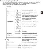
If you are using an actual encoder input, and want to use DirectSoft Quadrature Encoder Mode 40, then you will need some rungs that do the functions shown in the attached picture. This is how you get high-speed inputs into the PLC. Once you have the input data, then you must use it to trigger your UDC counter.

Let us talk about UDC for a minute. Normally, the UDC counts BOTH directions UP and DOWN. The first top input causes an UP count, and the second center input causes a DOWN count. Used with a high-speed quadrature input, Phase A goes to the UP input and Phase B goes to the DOWN input. If Phase A goes ON before Phase B, then the UDC counter counts UP, and if Phase B goes ON before Phase A, then the counter counts DOWN. Using Quadrature Encoder Method 20, you only really need ONE UDC instruction, which will count either direction. However, you should be able to make it work using TWO UDC counters, if they have different addresses. The disadvantage in using TWO UDC counters is that the counter does not actually record (track) the real physical position of the milling machine head. If you use ONE UDC counter, its value can be the actual physical location of the external device.

It is very hard to help you with this, because there is so much in you classroom PLC set-up that I do not know about. I cannot see if you actually have a real encoder input, or are just "simulating" encoder inputs.

Please, which Quadrature Encoder method you are using: 40 as you said, or 20 as you wrote in your program?

DirectSoft Quadrature Encoder Mode 40.jpg
 
Last edited:
Alimary,

In your last TIMER program, using two UDC counters, I think that both of your counters are going to count only DOWN. They will count DOWN because your are first turning on the UDC first top input, then after your 5-scond Timer reaches "5", you turn on the second center input. Remember, if the center input goes on first, the UDC counts only DOWN.

Normally, the way you would set this up would be to use only one UDC, with inputs that can make it count either direction, depending on which input goes on first. In this case, you start your counter at "0" position of the milling machine, and make it Count UP as the machine head moves (in the Right direction?), then when the head reverses direction (going Left?), the UDC counter reverses and counts down, all the way back to the 0 position. In this way, your UDC count value truly represents the actual position of the milling machine head. This is the way a real machine would be set up: the PLC counter value moves as the machine head moves. This method makes it much easier to work with the variables.

However, your method can be made to run - with many headaches, much hair-pulling, and sleepless nights of agony!

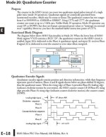
DirectSoft Quadrature Encoder Mode 20 is shown in the picture.

DirectSoft Quadrature Encoder Mode 20.jpg
 
Last edited:
I don't understand what is wrong, and why I cannot obtain the delay between the two outputs!
Okay, after much searching, I think I found an answer to your question. See the highlighted sentences in the attached picture of DirectSoft User Manual, Appendix E, page E-21.

In your program, you SET C21 Enable_Counter_L and C11 Enable_Counter_R. But you do not RST C21 and C11 immediately after the count. On the second pass of the PLC loop scan, these input bits will be still ON. This means that the UDCs are NOT working as Quadrature Encoder Mode 20 Counters. With C21 and C11 always ON before C16 and C20 (after first pass), the two UDCs will instead run as simple Up-Down Counters, and will always Count Down. If you want to use Mode 20, then add RSTs immediately after the UDC rungs to reset C21 and C11.

EDIT: The Mode 20 is a little "dance" between the two UDC Inputs. For your Rung 14:
1. C17 goes ON on Scan 1,
2. C11 then goes ON on Scan 2, causing 1 count,
3. C11 must now go OFF on Scan 3, so that C17 can go ON first for next count,
4. Now repeat Steps 1-3 for EACH new count.

Note that if you have real encoder Phase A and Phase B inputs, that you do not have to worry about manually doing the logic "dance", because the encoder does the sequence for you.

For a complete ladder logic setup of Quadrature Encoder Mode 20, see the second attached picture of page E-22. You may need to ZOOM these pictures to about 150% to be able to read the text.

If you are using real physical encoder inputs, note that for Mode 20 setup, certain data value must be loaded into specific V-memory locations (using SP0 first-scan bit that is ON 1 scan when PLC is first turned to RUN mode). It could be that your instructor is doing these for you, or your classroom DL-05 is already setup for Mode 20. If not, then you need to include the SP0 rung in your Initialize routine.

DirectSoft Quadrature Encoder Mode 20-E21.jpg DirectSoft Quadrature Encoder Mode 20-E22.jpg
 
Last edited:
Okay, after much searching, I think I found an answer to your question. See the highlighted sentences in the attached picture of DirectSoft User Manual, Appendix E, page E-21.

In your program, you SET C21 Enable_Counter_L and C11 Enable_Counter_R. But you do not RST C21 and C11 immediately after the count. On the second pass of the PLC loop scan, these input bits will be still ON. This means that the UDCs are NOT working as Quadrature Encoder Mode 20 Counters. With C21 and C11 always ON before C16 and C20 (after first pass), the two UDCs will instead run as simple Up-Down Counters, and will always Count Down. If you want to use Mode 20, then add RSTs immediately after the UDC rungs to reset C21 and C11.

EDIT: The Mode 20 is a little "dance" between the two UDC Inputs. For your Rung 14:
1. C17 goes ON on Scan 1,
2. C11 then goes ON on Scan 2, causing 1 count,
3. C11 must now go OFF on Scan 3, so that C17 can go ON first for next count,
4. Now repeat Steps 1-3 for EACH new count.

Note that if you have real encoder Phase A and Phase B inputs, that you do not have to worry about manually doing the logic "dance", because the encoder does the sequence for you.

For a complete ladder logic setup of Quadrature Encoder Mode 20, see the second attached picture of page E-22. You may need to ZOOM these pictures to about 150% to be able to read the text.

If you are using real physical encoder inputs, note that for Mode 20 setup, certain data value must be loaded into specific V-memory locations (using SP0 first-scan bit that is ON 1 scan when PLC is first turned to RUN mode). It could be that your instructor is doing these for you, or your classroom DL-05 is already setup for Mode 20. If not, then you need to include the SP0 rung in your Initialize routine.

Hello,
sorry for late reply and thanks so much for your help!
I want to ask you excuses because i am creating troubles on you by me typing in a hurry! The mode i am using its Mode 20 not 40!!! sorry to be so misleading to you!! I am using in my software two counters each one address to a different memory location!

however i came here to tell you that i solved my problem with the timers and i decided to not use them anymore so i will just be using my original software , and in particular to solve the mechanical coordination between the motor and the magnetic friction, i have decided to let the friction be powered up by the operator manually before making all the milling machine be running! this way i simplify my problem and i avoid using the timers because i must present this project for an exam and i am in a very short times!

I want to apologize to you for my incorrect informations about this morning because i was running from a class to another one and i confused the use of the different modes of the PLC.

I thank you so much for your time and explanations i now have a better understanding of the PLC logics regarding the timers and even if i won't be using them for this project, all your info will may be handy to me for the future!

thank you so much and again sorry!!!

Maria
 
Maria,

No problem. I am glad that you got it working. I was really puzzled! Seemed to be some conflict between 40 and 20.

You asked about using OUT instead of SET. I will try to create and show you an example of the differences. Each type of instruction has its uses.

SET is good where you need to turn something on and leave it on for awhile until some future event. OUT is good for things that go on and off often and at random times, for example an operator pressing a Start pushbutton. I will write a short DL-05 to demonstrate this, if you are interested.
 
Maria,

I thought that using your existing program would be the best way to show the use of the OUT instruction, and compare it with the SET instruction. If you look at Rung 15 in the attached "TIMER-Lancie1.zip" DirectSoft DL-05 program, you can see how it is used for the Y0 Motor Output. Notice that this rung now contains the one and only Y0 output in the entire program. If something goes wrong, the timers will go off, and Y0 will go off, without the need for a RST instruction to stop the motor.

While I was "operating" on this monster, I also made changes that I THINK will allow the timers to work to add the delays that you originally wanted! One of the big changes was deleting the Preload Pulse PD one-shot instructions. These are not needed in this case, because you are "preloading" CTA76 in other rungs. This should allow the counters and timers to operate correctly. I added to the rung comments to explain other suggested changes.

I also attached a PDF print-out of the program.

Best Regards, Lancie
 
Last edited:
Maria,

I thought that using your existing program would be the best way to show the use of the OUT instruction, and compare it with the SET instruction. If you look at Rung 15 in the attached "TIMER-Lancie1.zip" DirectSoft DL-05 program, you can see how it is used for the Y0 Motor Output. Notice that this rung now contains the one and only Y0 output in the entire program. If something goes wrong, the timers will go off, and Y0 will go off, without the need for a RST instruction to stop the motor.

While I was "operating" on this monster, I also made changes that I THINK will allow the timers to work to add the delays that you originally wanted! One of the big changes was deleting the Preload Pulse PD one-shot instructions. These are not needed in this case, because you are "preloading" CTA76 in other rungs. This should allow the counters and timers to operate correctly. I added to the rung comments to explain other suggested changes.

I also attached a PDF print-out of the program.

Best Regards, Lancie

Hello lancie,
Woow thank you so much for your efforts!!!! I will check this new program of my plc so I can eventually modify my project if it will work correctly!!! Thank you so much!
Today I also went reading the out istruction into the dl05 manual and I understood more about it and actually its very simple to use it and it is useful for the pushbuttons a lot!
Surely your help will come me handy because I really liked working with plcs and I hope in future to return working on them (maybe for work more than study reasons!!)
I will check the software in those days and report to you about the results!!!
Thank you again for your patience and time!!!

Regards,maria
 

Similar Topics

Hi everyone I am using Winproladder software for programming FATEK FBs PLCs and in programming, we often use Timers for activation of the...
Replies
4
Views
576
Hey guys, I am trying to pull the ladder logic out of some ancient Honeywell S9000 PLCs, but I can't find the software anywhere (google search...
Replies
10
Views
4,881
Dear all pls help me.. What is the HSD NC unit ladder software name for troubleshooting... Software used in Biesse Wood cutting machine...
Replies
2
Views
1,039
Please I want software to convert grafcet to ladder:shock::confused::confused:
Replies
3
Views
4,545
setup Clients Plc is a Keyence KV3000 my SW is KVstudio 7.0 English version. Logic and plc in Chinese task Add 3 seconds (delay off timer) to...
Replies
2
Views
3,585
Back
Top Bottom