Hooking up a heater to a MicroLogix 1000

SergioB

Member
Join Date
Dec 2011
Location
Chicago
Posts
119
Hi all and happy holidays!

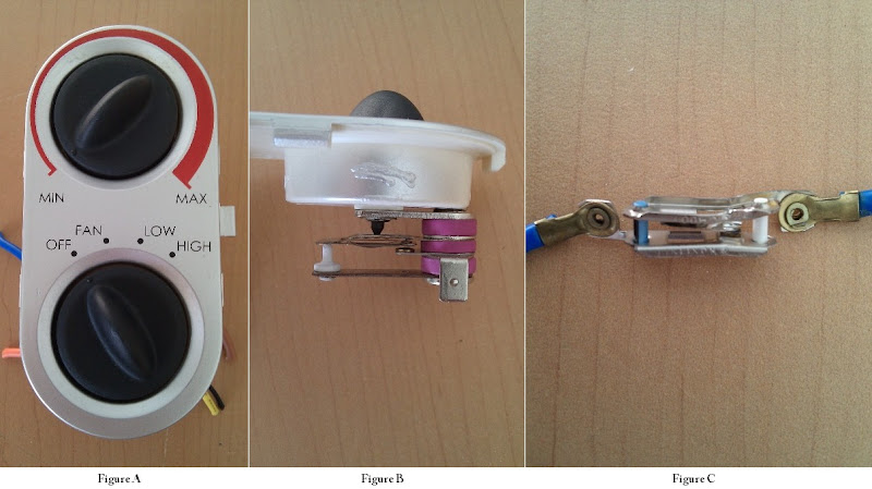
I'm self-teaching PLC wiring/programming and I'm currently working on controlling a 450W electric heater. I eventually want to hook it up to a SLC-500 with an analog card, temp sensor and PanelView C600 and be able to set Manual and Auto mode, with temp setpoint, etc, but for now, I'm just playing with the wiring on my ML1000 (cheaper if I mess it up, hehe)

The problem is that I only have a limited selection of relays and have selected the following for my experiment:
1 DPDT, 24VDC, with allowable contact power of 1540VA, 300W, 10A relay
3 SPDT, 24VCD, with allowable contact power of 1540VA, 300W, 10A relays

It appears that I will only be able to power on the heater for a few seconds, just for testing purposes until I can get relays with a higher-rated load.

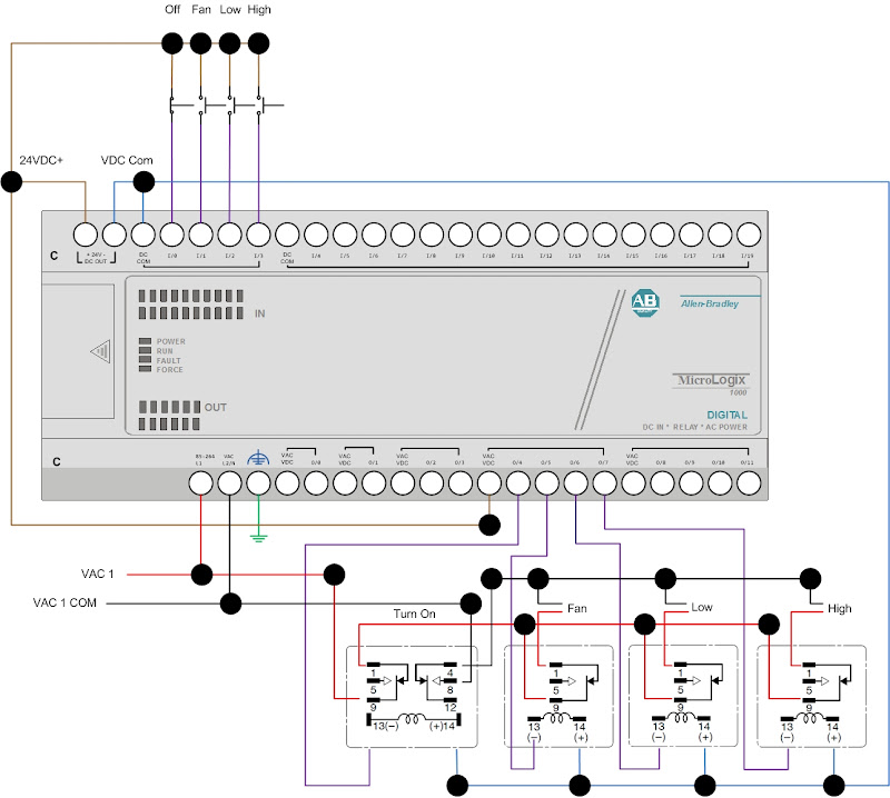
I'm obviously not going to run the AC loads through the internal PLC coils, I'm only going to use the built-in 24VCD power supply to activate (close) the relay contacts. I want to run the AC loads through the relay contacts as shown in the following diagram:

MicroLogix%2525201000%252520%252526%252520Hampton%252520Bay%252520Heater%252520Wiring.jpg

I'm new at making electrical wiring installations (my background is in c++ development), but find this field extremely interesting and rewarding. I'm also learning electrical circuits, etc as time permits.

My question/concern is: Am I correct in assuming that the way I'm wiring the AC loads, isolate the PLC coils completely and there's no risk of damaging it?

Thanks in advance!!!
 
Last edited:
Sergio,

Happy Holidays and Happy Programming!

Yes, your circuit will not harm your PLC.

Other tips:
(1) You do not need to wire the heater Common (neutral white wire) through a relay. Normally, the neutral wire is not switched, so wire it up directly to the heater.

(2) Instead of using the double pole relay to turn on your power, use it to turn on Heater High. Each pole is rated 10 Amps, so by using two poles in parallel you can switch a 20 Amp load (minus some derating for heating of the relay). Certainly you should be able to handle the 450 watt heater high element. Then use the one pole relays for Low and Fan.

(3) You really do not need 4 relays. You only have 3 separate functions (Fan, Low, and High) so 3 relays will work just dandy. Your PLC program can determine if Low or High outputs are ON, then autmatically turn on Fan.
 
Last edited:
GREAT!!!

1) You're right, I've never seen a neutral line going through a relay either.
2) Good idea about using the double pole relay for the high setting!
3) Good point!

I will make all the changes you suggested.

Thanks a lot!!!

Cheers and have a great time during the holidays!
 
Last edited:
Also, don't forget circuit protection (fuses or circuit breakers).

And, for safety reasons, every heater circuit I have ever worked on has some sort of "air flow proving switch". Sometimes they are very simple mechanical switches that swing when the air is moving, other times they are touchy little low pressure switches that sense the vacuum created on the back side of the fan.

In any case, they're usually hardwired so the heater can't operate unless the switch is made (don't depend on a PLC program and/or relay to function) This keeps the house from burning down because the fan blade fell off the shaft, or because a squirrel crushed the exit duct, or ???

And, although you can in theory double the current carrying capacity of a relay by wiring contacts in parallel, in reality, one contact ends up carrying most of the load especially when opening and closing, so a single power relay is much preferred. If you do the parallel contacts within a single relay, it will work much better than two separate relays because the timing of the contacts opening and closing will be more consistent.
 
Last edited:
And, although you can in theory double the current carrying capacity of a relay by wiring contacts in parallel, in reality, one contact ends up carrying most of the load especially when opening and closing, so a single power relay is much preferred.
True, but in this case the heater max is 450 watts/120 volts = 3.75 Amps, so one 10 Amp contact should be enough, but two will add insurance and durability.

Sergio, double-check your maximum heater power. 1500 to 1800 watts is more common for household heaters, but you may have a smaller one.
 
Yup, it's a very small heater, about 14" x 10" including the enclosure. The heater only says "127 V ~ 60Hz 1 450 W" on the bottom and does not show max rating.

Regarding circuit protection, the heater had 2 safety switches (shown below).

IMG_20111224_153653.jpg


The Min/Max dial (Figure A), has a safety device of sorts (Figure B). Contact opens as wires (or internal compartment?) heat up, so the dial needs to be turned up as heater (or wires) heats up.

The second safety device (Figure C) was placed between the heater elements, in an area where no direct heat would reach it, but perhaps close enough to detect overheating of the heater element assembly. This safety device was already partially damaged due to me tinkering with it in the past, but I noticed that this device opened while being outside where it was originally placed, so it opens just as wires heat up due to resistance, so not sure if this is normal...

The "air flow proving switch" you mentioned sounds really cool OkiePC, but it seems like the safety device used for the Min/Max dial is pretty reliable, so I'm thinking about using this as a safety disconnect device for now. What do you think?

Thanks,
sb
 
I'd suggest that figure B is a bi-metallic thermostat, not a safety device. Figure C, yes, likely a safety device.

Shawn
 
The Min/Max dial (Figure A), has a safety device of sorts (Figure B). Contact opens as wires (or internal compartment?) heat up, so the dial needs to be turned up as heater (or wires) heats up.

That looks like a thermostat to me. Not a safety device.

The second safety device (Figure C) was placed between the heater elements, in an area where no direct heat would reach it, but perhaps close enough to detect overheating of the heater element assembly. This safety device was already partially damaged due to me tinkering with it in the past, but I noticed that this device opened while being outside where it was originally placed, so it opens just as wires heat up due to resistance, so not sure if this is normal...

Does this device's contacts open when its not in it's original upright mounting position? Because it looks like a tip over disconnect.
 
How embarrassing that I didn't recognize a thermostat! Sorry.

Hi Vaughn, nop, this device's contacts are not affected based on its position. Contacts open based on wires overheating.
 
Sergio,

Most residential heaters do have a tilt switch, and Figure B switch may have a counterweight that shifts position if it is not vertical, so that a tipped heater will be shut off.

In any case, it looks to me like your power rating is 1450 Watts, not 450 watts. That is closer to what I would expect. Now you have to figure out how much power is required for the High and Low settings. Usualy there are two elements, and High switches power to both of them. The 1450 will include the fan power also.

So now you are up to 1450/120 = 12 Amps, and you do need both 10 Amp contacts of your relay to handle that on the High setting.

Does the fan run faster on the high setting? Many heaters with two heat ranges have a two-speed fan.
 
Most residential heaters do have a tilt switch, and Figure B switch may have a counterweight that shifts position if it is not vertical, so that a tipped heater will be shut off.

This one is not visible anywhere, but once reconnected to PLC will have to actually tilt it while it's on to see what happens.

In any case, it looks to me like your power rating is 1450 Watts, not 450 watts. That is closer to what I would expect. Now you have to figure out how much power is required for the High and Low settings. Usualy there are two elements, and High switches power to both of them. The 1450 will include the fan power also.

So now you are up to 1450/120 = 12 Amps, and you do need both 10 Amp contacts of your relay to handle that on the High setting.

Wow, it makes sense. There's a space between the "1" and the "450", so I completely missed it!

There are two elements, only one turns on when on "Low" setting and both turn on when on "High" setting.

Does the fan run faster on the high setting? Many heaters with two heat ranges have a two-speed fan.

This I don't remember, but will test it as well, once re-wire the heater and fan and hook it up to the PLC.

Will keep you posted...

Thanks a lot!
 
I'm just playing with the wiring on my ML1000 (cheaper if I mess it up, hehe)
I know what you mean, but think of it as learning or training. Never think of this serious process as playing.

People have been killed as a result of poor PLC programming, and that takes it out of the play category. Also make sure you do not hurt yourself while "learning" about circuit wiring. Learn to double-check yourself before turning on the 120 volt power.

If possible, get a 24 VDC motor, heater, or other device for training, instead of the 120 volt heater.
 
Last edited:
Thanks for the advice Lancie1!

I actual have 2 DMMs and always have them readily available to test continuity and voltage and a labeler to properly identify wires, before flipping the "ON" switch.

So, in my case, my "playing" involves a great deal of precautions. It doesn't hurt to have a mild case of OCD either, he he!

Cheers!
sb

My workstation:
IMG_20111226_150702.jpg
 
Last edited:
just think of this process as self-teaching, like you said before. That could be worth thousands of dollars in your career, if your boss hears you talk about "self-teaching" instead of "playing". People are not usually rewarded for merely playing.
 
Good point. I'll make sure replace "playing" with "self-teaching" from my vocabulary in order to come across more professionally.

Thanks!
sb
 

Similar Topics

Very simple/basic question, but I want to get rid of my uncertainty. I don't think it would be an issue, but when I'm the one writing the program...
Replies
2
Views
1,413
Hi guys, I'm a student starting to study PLC programming and in the class that I am in we don't really get into hooking up to a PLC using an RS232...
Replies
7
Views
3,483
I have an application that has a G310 talking serially to an Allen Bradley Micrologix 1500 PLC. I would like to add a second G310 at another...
Replies
10
Views
4,536
Oh boy! Another HMI design possibility just fell in my lap! I'm stuck on one thing, though... I'm not sure what to recommend for input...
Replies
11
Views
3,113
WE have a ab 5/15 on a compressor when one of the techs hooked a hart475 to a discharge pressure tramsmitter , the compressor shut down on surge...
Replies
4
Views
3,780
Back
Top Bottom