Siemens Step 7

Tim J

Member
Join Date
Oct 2002
Location
Walled Lake
Posts
10
I am taking a crash course (sink or swim) on Siemens Step 7 software. I don’t have a PLC to work with, so I am using the PLC simulator. We are working with two different processors, a CPU 319-3 PN/DP, and a CPU 315F-2 PN/DP. Most of the programs are already written, so my job is to translate the STL to ladder. I have so many questions, I’ll just start with a question or two.
When on line with the simulator, I want to turn bits on and off. It appears you can only do this with inputs (I can’t find a way to manipulate internal bits). My problem here is that even the inputs seem to work sometimes. I can right click on the element, and I click Modify to 1 (or 0). Sometimes the contact will change state, most times it won’t. I can click Control at Contact from the Debug menu, and that doesn’t seem to have any effect. I can open the simulator PLC and click on insert, then click on Insert Input Variable, set the address, and check the inputs I want to go high or low, and this seems to work every time. Is this the only way to manipulate Input bits and can it be used to manipulate internal PLC bits like M bits or data block bits? And what about bits in the declaration section of a block itself that are used in the block, is there a way to turn these bits on and off?o_O
I have many questions about STL, but this is a good start.
Thanx to anyone who can help!
 
Its a lot easier to learn STL, Siemens has classes in GA

I did one before but I was programming and troubleshooting for a few years before I did it.... it was a small program and took a few weeks (not full time) but it also took about an hour to get tired of doing it

On the plus side, once you are done you will know how to program a little better :)

Do you have a spare CPU? I would build a trainer, this way you can fire real I/O... makes it a little easier
 
Re simulating inputs:
PLCSIM is a bit different than a real PLC in this respect. Best is to manipulate inputs by PLCSIM itself like you have found out yourself.

Re Merker and DB addresses:
Can be manipluated with PLCSIM, in variable tables, or online in the code editor (select the address, rightclick, and select "modify").

Re addresses in a declaration:
For FCs, there is really no way to manipulate the internally declared addresses. In stead maninpulate the addresses that are forwarded to the FC.
For FBs, you can manipulate the declared STATs with PLCSIM or VATs. Dont think you can manipulate the STATs while online in the code editor.
 
Tim J , If you have the actual application and Step 7 software installed on your computer and all the logic is viewed as STL why can't you just change the view to LAD? This won't convert every rung of logic to ladder logic but at least it will give you an idea on how STL is structured compared to LAD.
 
Tim J , If you have the actual application and Step 7 software installed on your computer and all the logic is viewed as STL why can't you just change the view to LAD? This won't convert every rung of logic to ladder logic but at least it will give you an idea on how STL is structured compared to LAD.

If the program is written in STL then it will almost certainly not convert to ladder. It is a good idea though to change view on any ladder to STL and back again. If there is none, write lines of ladder just for this purpose.
 
That's how I started learning STL. Looked up the instructions in the Help file, then did my best to re-write the Network in a new Network in LAD, and converted the new LAD Network to STL to see how close I was. Lots of branches and the O( ) stuff in STL still makes me have to stop and think though. I understand them, it's just not as quick to see what's going on as it is in LAD.
 
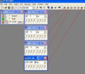
Here's a screen shot showing PLCSIM in use for various variables. If the plc code is writing to a variable (it can write to the inputs), then if you modify it the program will simply write the value back according to the processing logic.

plca1.JPG
 
Thank you all. I have tried many of your suggestions and have found them very helpful. Double checking the STL by writing ladder then switching views works pretty good, but it was surprising to see all the 'extra' code I wasn't expecting.
Thanx again
 
Its a lot easier to learn STL, Siemens has classes in GA

I did one before but I was programming and troubleshooting for a few years before I did it.... it was a small program and took a few weeks (not full time) but it also took about an hour to get tired of doing it

On the plus side, once you are done you will know how to program a little better :)

Do you have a spare CPU? I would build a trainer, this way you can fire real I/O... makes it a little easier

Thanx, I wish I were in GA this time of year! We are trying to obtain a CPU, the request has to go through channels, of course, and the cost has to be justified, but we are working on it.
 
Here's a screen shot showing PLCSIM in use for various variables. If the plc code is writing to a variable (it can write to the inputs), then if you modify it the program will simply write the value back according to the processing logic.

Thanx, I did find the IB and QB, but didn't know this would work for MB and DB.
 

Similar Topics

Good Morning, Hoping someone with some Siemens experience can give me a hand with this one. Customer has a S7-200 cpu, which has a 6GK7...
Replies
0
Views
245
I'm just trying to figure out the right method of adding a DO card to an existing rack. It's not the *next* open slot, but I have to move the AO...
Replies
5
Views
546
Hi Siemens Experts, I am hoping someone can shed some light on my issue. I have uploaded the code from a S7-300 (317-2PN/DP) using Step 7...
Replies
9
Views
667
Hello, We monitor the temperature of a pipe via a 4-20mA temperature transducer. This goes into DB135(Read Analog Inputs). The issue I have is the...
Replies
0
Views
624
Please excuse the basic question, but I've never worked on Step 7 before (until now, only dealt with Mitsubishi Q-series PLCs)... What is the...
Replies
16
Views
3,326
Back
Top Bottom