Please help!

Chevy01

Member
Join Date
Jan 2012
Location
Red Deer
Posts
7
I am wondering if anyone can help? I am working with an AB pico mini plc. I want to make the output relays normally closed( open on an input fault condition)

Thanks!
 
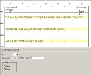
For the Allen-Bradley Pico PLC, it would look like this: (Notice the line right above the I01 input, which indicates a "Break" contact (on when physical input is off).

FAULT CONDITION INPUT-BREAK.jpg
 
Last edited:
Maybe you could help with the whole project? I have five inputs. Four of them have the same function. If any of these four inputs "open", then I would like the output Q1 to open as well. In addition, I would like to display a text descriptor for each input when in fault. The fifth input will open outputs Q1&Q2, as well as display a text descriptor. I want the outputs to latch open until the I8 contact is mOmentarily closed ( reset button).
The outputs must be closed until an input is opened
 
You have almost fully described the program in "pseudo-code".

I suggest that you replace the terms "open" and "closed", which might apply to physical switches, and use "True" or "False", which apply to the Boolean data types for both inputs and outputs.

Describe exactly what you mean by "text descriptor"; are you talking about a text object on the Pico (is it a GFX model ?) or something else ?

It would help to post the whole part number of the Pico controller and which software you're using with it. That way if somebody posts a Pico program in its native format (not a screenshot) you can open it correctly.

One thing you'll find here on the Forum when learning (and especially when doing homework) is that the help you get is proportional to the effort you display. Go ahead and post a screenshot of how *you* think the logic might look.
 
I am using a pico 1760-L12BWB. By text descriptor I mean using a text display that is shown on the display of the pico.
I am just posting with my I-phone so I can't post what I have so far...

Thankyou for any and all help!
 
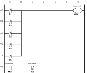
My contribution: here's how I would latch a "fault detected" marker bit M1 in the event of any of the I1 through I5 inputs going false.

You'll need another rung to detect I5 going false itself, since that has a separate meaning.

And you'll need one rung each to control Q1 and Q2.

Latch Fault Inputs.png
 

Similar Topics

Hello, I am trying to get a Yokogawa Hart pressure Transmitter and a Rosemount Temp Transmitter to read on a 1769-IF4 module on an L33ERM...
Replies
10
Views
375
Please help me, I have solve many week but still not solve it. I found trouble of factory talk studio when I set tag by browse address of OPC...
Replies
0
Views
117
Hello Everyone, i Have im my Industry a Endress & Hauser Promag400 this has a screen that constantly have that error, it says to wait, somebody...
Replies
2
Views
475
After replacing the 70 with the 525, the PLC can read from the drive and recognizes it as online, but no commands are being listened to. PLC is...
Replies
1
Views
551
Back
Top Bottom