difference between S7 and RS500 timers

bgkdavis

Member
Join Date
Jan 2012
Location
brisbane
Posts
13
Is it the case that the elapsed time registers in S7 count down whilst in RS500 (.ACC) they count up?

I've the following block of 7 code, where T33 is a 6 second timer

L "T33"
L 535
>=I
= "M21.0"

This suggests to me that M21.0 is true for the first 0.65 seconds of the timers operation, and the equivalent RS500 block would be

LES T4:82.ACC 65
 
If the Siemens register is described as "elapsed time", and it counts down, then they have invented a time machine.

INHO, elapsed time can only be an increasing value.

Sorry, no experience with S7, but in A-B world the timer .ACC value starts at zero, and accumulates time to the preset .PRE.
 
Putting the unnecessary pedantry aside...

Yes I'm aware that the RS timer registers count up (elapsed time units if you wish), what I really need confirmation of, is that the S7 timer registers count down (remaining time units).
 
As I said the last thread, do a search on here to find other threads, S5Time has been done to death.

No, the timer goes up.

Its BCD 000 to 999.

the time base is in the first 4 bits

x.yyy x = time base, yyy = BCD value
 
Putting the unnecessary pedantry aside...

Yes I'm aware that the RS timer registers count up (elapsed time units if you wish), what I really need confirmation of, is that the S7 timer registers count down (remaining time units).

The following is from the S7 help file for a S_ODT timer -

"S_ODT (On-Delay S5 Timer) starts the specified timer if there is a positive edge at the start (S) input. A signal change is always necessary in order to enable a timer. The timer runs for the time interval specified at input TV as long as the signal state at input S is positive. The signal state at output Q is "1" when the timer has elapsed without error and the signal state at the S input is still "1". When the signal state at input S changes from "1" to "0" while the timer is running, the timer is stopped. In this case the signal state of output Q is "0".

The timer is reset if the reset (R) input changes from "0" to "1" while the timer is running. The current time and the time base are set to zero. The signal state at output Q is then "0". The timer is also reset if there is a logic "1" at the R input while the timer is not running and the RLO at input S is "1".

The current time value can be scanned at the outputs BI and BCD. The time value at BI is binary coded, at BCD is BCD coded.
The current time value is the initial TV value minus the time elapsed since the timer was started."
 
Last edited:
OK, I've now got directly contradicting information here, some are saying they count down and others count up, maybe the confusion is due to specific registers, I don't know... maybe if someone was to make reference to the code I've quoted then the potential for confusion could be avoided.

Unfortunately I'm not in a position to select which S7 timers that are used since I'm trying to transcribe an S7 program (from PDFs) into RS500, so I need to have a perfect understanding of the exact functionality of the used S7 timers, such that I can develop equivalent code in RS500
 
The timers "count down" to zero, From the Hans Berger Books -

When a timer is started, the CPU uses the programmed
time value as the timer's running
time. The operating system updates timers at
fixed intervals and independently of the user
program scan, that is, it decrements an active
timer's time value as per the timing period indicated
by the time base.
When the value reaches zero, the timer is
regarded as expired. The CPU then sets the
timer status (signal state "0" or "1", depending
on the type of timer involved) and drops all further
activities until the timer is started again.
 
Thanks, this looks good, and after rereading your previous post I can see that its pretty much in agreement with what you wrote earlier.... and a little less ambiguous
 
S7 instruction list

S7 Documentation

S5 counters can count up and down, depending on instruction used.

Code:
A C1

Will result as true if counter value is more than 0 and if 0 then it will result as false.

Timers are more complex, everything depends on timer type. Best would be to get help files, i'm not sure but maybe S7 Lite has help files with it, its free.

S7 Lite
 
Forget the S5 timers. Use the IEC timers. They are very similar to the AB timers. Counts up for example, just like AB timers.

O..
Unfortunately I'm not in a position to select which S7 timers that are used since I'm trying to transcribe an S7 program (from PDFs) into RS500, so I need to have a perfect understanding of the exact functionality of the used S7 timers, such that I can develop equivalent code in RS500

Jesper, you did one "junior dont" in here 🍻
 
I can fully appreciate the difficulties in converting applications S7 to RS500 when you come across the S7 "time-value" from a timer as a decreasing value (Preset down to zero).

All you have to do is remember that timers are always used for generation of delays (they can't be used for anything else !).

If the "time-value" (that's the .ACC in A-B speak) counts down, and the program is looking for an "elapsed" time, then there will have to be some additional code doing the maths. Programmers like to do things like look at timer elapsed times to do things at certain times.

Perhaps there's a "Greater Than" instruction, which for S7 will go false after a specific time. In A-B we would have to use "Less Than"....

and vice versa

Good luck with your conversion.

BTW A-B Rules ! (my 2c)
 
Lancie, please do not mix Timers and Counters. Your post is cluttered and confusing with references to both timers and counters.

There are only three "timer" instructions in all A-B platforms

TON
TOF
RTO

Please explain why you introduced Counters into the discussion ?

edit : I guess Lancie deleted his post
 
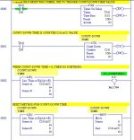
Okay, my age-riddled mind was trying to point out why AB did not see any need for a Count-Down Timer, when the Count-Down Counter will do the same thing. Here it is, an Allen Bradley Count-Down Timer.

COUNT-DOWN TIMER.jpg
 

Similar Topics

Hello, I have a problem with AO- and AA-Tags. When I use for example the tag AO_Test with the address 200 and type the value 1,2 in, the AA-Tag...
Replies
7
Views
1,407
As per the title. This might seem like a basic question to many, but I'm unclear about the difference between a coil ( ) and an application...
Replies
28
Views
4,015
Good Morning , I have 2 Frequency Drive panels to build and commission . It is for 2 pump systems . Just wondering , what is the...
Replies
4
Views
1,963
Hi Experts, Good day! What are the differences between PCS7 SIMATIC Batch and PM Control? Do you have any manual like "Getting Started "...
Replies
0
Views
807
I have a Automation Direct Click Plus that you can buy option CPU slot modules for input/outputs. The slot modules have the options of sinking...
Replies
9
Views
2,810
Back
Top Bottom