Omron Zen Programming question ...

Ron Beaufort

Lifetime Supporting Member
Join Date
Jul 2002
Location
Charleston, SC
Posts
5,701
I had a new member call me earlier - and since I don't do Omron, I suggested that he post his question here ... he is in the process of joining the forum - but there might be a (security) delay in how soon he is allowed to post ...

I offered to post the question for him - hopefully the forum will be able to give him some guidance ...

Ron,

Here is my question. Thanks for posting it for me.

I have an Omron Zen with 4 outputs (Q0-Q3)

I am trying to set it up to control three outputs with timers. Each Input does a different timer, but some share outputs and the software keeps giving me an error with duplicate outputs. An example of what I am trying to do is below.

Input I0: Output Q0 for one minute.
Input I1: Output Q0, Q1 for one minute.
Input I2: Output Q0,Q1 and Q2 for one minute.

I understand how ladder logic and if/then works, but I don't know how to make the software do this. I can make it work as long as there are no shared outputs. I am completely new to PLC programming but I can do this if I can get past the problem I am having now. Is there any way to share outputs?

I have spoken to someone at Omron who got me started, but he told me to "play with it a while then call if I got stuck". I called him back and he told me how it could be done but didn't want to help me any further. I need someone to SHOW me how to do it.

Thanks in advance for any help!
--
Shawn
 
in the meantime, here's something in an Allen-Bradley format that I think would answer the question ...

notice that no "interlocks" are provided - in case someone turns on two inputs at one time, etc. ...

.
 
I have a followup question:

How would I trigger relays to turn on for set amounts of time?

I am looking at purchasing either the Omron or Eaton programmable relay for some really simple process control but it's not absolutely clear to me if it's possible. I haven't been able to pick out specific examples in the user manuals.

I basically just want:
Trigger start
relay 1 on for 10 minutes
then relay 2 on for 10 minutes
then relay 3 on for ten minutes
then everything resets and is ready to be triggered again.

....so one trigger for 3 sequential events.

I guess you don't have to explain if it's a tedious task. Maybe just confirm for me that this is one of the functionalities that the relay is intended for so I should be able to figure it out once I buy it.

Thanks in advance!

p.s. I'm a mech engr with no ladder programming experience. Basically just MATLAB stuff to process data.
 
Oh wait, I'm rereading the original post. So it sounds like timing is standard and things don't have to be turned off by an external trigger.

So can I have internal triggers? i.e. relay 2 is triggered by the timer of relay 1 hitting 0
 
So can I have internal triggers? i.e. relay 2 is triggered by the timer of relay 1 hitting 0
Yes, you can use "M" internal relays in the ZEN, but you might not need an internal relay for every timer. Each timer also has it own output contact that goes closed (or open) when the timer reaches some value. In the ZEN, the timer preset value is actually set by using a timer contact, where you define the time period.

In Moggie's program, relays were used to control PLC outputs, but the timer outputs could also be used directly in most cases.

Would it help you for me to post an actual ZEN program that would do the tasks you described?

I haven't been able to pick out specific examples in the user manuals.
You will not be able to because they aren't there. That has got to win a prize for the most poorly written PLC manual. I think it was written by a bunch of journalism graduates.

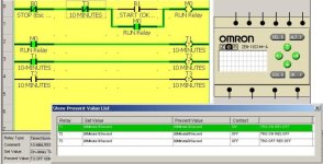
EDIT: Here is your ZEN program, in Simulator Mode with Timers set for 10 seconds instead of 10 minutes to shorten the test period. In the picture, T1 has reached 10 seconds. When T2 and T3 reach 10 seconds, the RUN relay will be deenergized. The timers are automatically reset to 0 when their input triggers are deenergized.

TAL508 Timers.jpg
 
Last edited:
Input I0: Output Q0 for one minute.
Input I1: Output Q0, Q1 for one minute.
Input I2: Output Q0,Q1 and Q2 for one minute.
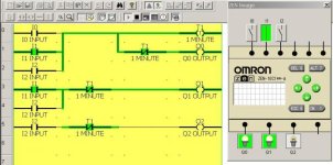
For Shawn's program, alternate interpretations could be valid, depending on the physical atributes of I0, I1, and I2 (whether they are maintained or momentary-contact) and whether the 1-minute period is inclusive for all inputs, or exclusive so that each starts a 1-minute period. Here is an example that assumes maintained-contact input pushbuttons, an inclusive time period, and meets all the requirements as stated with one timer. The moral is that good definitions and descriptions of logic are the first thing needed. Note that in this example, I1 is ON and Q0 and Q1 are ON and will stay ON for 1 minute as specified.

How do you arrive at this logic? First, I looked for all the time periods that could be identified (one 1-minute period) and put in that timer. Then I looked for all outputs (3) and put those in on the right side. Then I looked at each Q output and asked "what are the least number of instructions to turn on this output and turn it off again after 1 minute"? I focused my attention on the instructions that perform the work and the action - the outputs.

SHAWN Timers.jpg
 
Last edited:
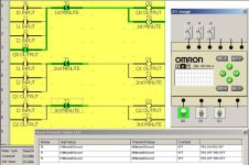
What if Shawn's 3 Inputs are really momentary-contact pushbuttons as used in millions of Start circuits all over the world? What if the time periods are exclusive and can start at different times? Now we have different logic than any shown so far. We must provide seal-in contacts to hold the timers on after the pushbuttons are released, and we must provide 3 timers for 3 possible time periods.

Here is an example that assumes momentary-contact input pushbuttons, three exclusive time periods, and meets all the requirements as stated with 3 timers and 3 ladder rungs.

SHAWN Timers Version 2.jpg
 
Last edited:
My program

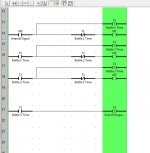
Just to close the loop. This is what I ended up doing to create my 3 cascading timers. M0 is triggered by a user input. T4 automatically triggers a stop command when the program completes. M1, M2 and M3 trigger the corresponding actions to each of the three timers. I've cut out the stuff not directly related to the timers.

Thanks again for all the comments!

3 cascading timers.jpg
 

Similar Topics

Hi All First time Post I have an Omron Zen that I am trying to program for a chemical delivery system. I have done a few simple programs before...
Replies
12
Views
2,158
Our local non profit railroad museum has a railroad signal that we need to program to operate in a specific manner. The lighting in the signal is...
Replies
23
Views
7,744
I am very new so I will try to give as much information as possible. I cannot get a Prolific PL-2303TA USB to RS232 to connect to an Omron ZEN...
Replies
1
Views
1,586
Hi, after 30 years involved with automation I'm actually writing my first PLC program and am struggling a fair bit. My background is mechanical...
Replies
8
Views
1,866
Hi I am setting a system up as per the attached picture, 5 inputs that are always present. These are sensors I have in an injection mould, if...
Replies
5
Views
1,847
Back
Top Bottom