Unproportional Speed using Powerflex 40

only1vip

Member
Join Date
Jan 2009
Location
Canada
Posts
11
Hey all,

I have a Powerflex 40 driving an SEW motor and am having trouble getting the motor to run at the speed I want.

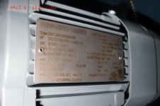
The label on the motor is attached, and I admit that I'm having difficulty interpreting this label, so I may have misinterpreted it. It is attached.

Set up for 50Hz, am I supposed to interpret this label as reading: at 50Hz, I will get 51RPM? Because that is the base scale I am using.

If so, problem is that I am not getting a proportional speed output when using that scale (when I lower the Hz, I am actually getting a lower RPM than expected, and vice versa).

Any ideas?

Thanks in advance for any feedback!
CIMG1385.jpg
 
Here in canada your base speed will be 60Hz, so 63rpm * 50/60 = 52.5 rpm. It may be your getting more slip then usual? How much lower then expected is it and is it a linear decrease?
 
Hey Christoff,

I am overseas on a project and base is at 50Hz.

Getting RPM differences of about 10%-20% both ways and they are somewhat linear.
 
Is the motor loaded or unloaded? How are the Amp/Load/Volt readouts from the drive? Can you try a spare motor to see if it performs the same.
 
Hey all,

I have a Powerflex 40 driving an SEW motor and am having trouble getting the motor to run at the speed I want.

The label on the motor is attached, and I admit that I'm having difficulty interpreting this label, so I may have misinterpreted it. It is attached.

Set up for 50Hz, am I supposed to interpret this label as reading: at 50Hz, I will get 51RPM? Because that is the base scale I am using.

If so, problem is that I am not getting a proportional speed output when using that scale (when I lower the Hz, I am actually getting a lower RPM than expected, and vice versa).

Any ideas?

Thanks in advance for any feedback!

I read label at 50 Hz you should have 1320 RPM and at 60 Hz you should have 1640. So RPM per Hz should come out to be about 26.

What the 51 after 1320 or the 63 after the 1530 values is all about I do not comprehend. Amount of slip at full load???
That does not make sense either - this should be a 4 pole motor thus synchronous speed of

1800 RPM at 60 Hz (160 RPM slip per nameplate seems high to me)

OR 1500 RPM at 50 Hz (180 RPM slip also sounds high)

Nameplate calls out for brake - Uhhh you do have this properly controlled ie brake is released when motor is running and NO drag??

Dan Bentler
 
Last edited:
Generally when I see motors labelled like that they have a built-on reducer, so motor is running at 1320rpm and the output shaft is 51rpm.
 
How do you have the motor connected? Is it connected in WYE/STAR? Or is it connected in DELTA?

Is the Powerflex 40 single phase input or 3 phase input? This will change whether the motor should be connected in WYE/STAR or DELTA..

Is the brake supplied separately from the Powerflex 40?
 
Set up for 50Hz, am I supposed to interpret this label as reading: at 50Hz, I will get 51RPM?

Dan already mentioned the excessive amount of slip this motor has (in excess of 10%). I'm wondering if "slip compensation" has been enabled in the drive, and if it's distorting your results. Or perhaps you need to enable the slip compensation?
 
This is a label from a Eurodrive gearmotor, I suspect. At 50hz, you will get 1320rpm motor shaft speed and 51rpm gearbox output shaft speed. The higher numbers 1640/63 would be if the motor is running on 60hz.

The input supply voltage to the drive defines the maximum avaulable output voltage so, if 230V you connect the motor in delta and if 400V you connect the motor in wye or star. Be sure you put the motor nameplate data into the drive parameters as you have it connected.

Eurodrive motors always seem to have a lot of slip. I don't know why that is. If you are configuring your drive for V/Hz control, the best you can do is get rid of about 1/2 the slip using slip compensation. If using sensorless vector control, you should be able to get down to 1/4 slip or even bette with the better drives. In each case above the slip ranges are from no-load to full-load.

Remember that when using a high reduction ratio gearbox, the internal friction losses tend to mask out some of the load changes so your actual slip with this high ratio gearbox will probably be less than the figures listed above.

As for the brake, be sure to control it thru a Run/Stop relay on the drive. Do not connect it directly to the motor leads in any case.
 
Wow...thanks for all the input, you guys are awesome!


I am working on the machines that were installed and programmed by a supplier that is no longer on site, so I do not have all of the answers to your questions yet.


I am only using the Start, Stop (XIO of Start bit), Forward, Reverse, and FreqCommand bits in the provided UDT to drive the VFD/Motor. Not sure of the brake that you guys have referred to?


I guess I may have to go into more detail to hopefully find an answer.

This may be lengthy...sorry.


This motor is connected to a belt which has a blade attached to it which cuts material under it. The blade cuts the second half of the material on the forward pass and the first half on the reverse pass. There is a bar which lifts the material at the center so the hooked blade can make the first penetration at center. The blade has to cut all the way to the edge of the material, but not leave the edge. If it leaves (goes further than) the edge, the blade can bump the newly cut (which curls up) material and produce an shifted cut on the reverse pass.


The material is cut at an angle and the actual width varies (trig is used to determine the actual length of the cut path). We are using a timer to determine when we should stop the cutter's motion once the cutter reaches the center (where we have a sensor).


Equation being used is below: Width is in mm, Angle is in degrees and CutSpeed is in mm/s


Timer.PRE=ABS((Width/(2*SIN(RAD(Angle))/CutSpeed*1000)


So by the equation, once we hit the sensor and the timer is done, the cutter should have reached the edge. This works fine when intially calibrated, but the cutter overshoots when the speed is increased and undershoots when the speed is decreased.


I went as far as video recording the motor shaft at different frquencies so I could determine the actual Hz/RPM ratio. I found that it is closer to 50Hz/55RPM. So I used the new ratio (converted over to linear speed =(RPM*2*PI*CutLength/2)/60) and I still am seeing that the cutter under and overshoots. I've monitored Acc/Dec time and they are negligible.


Hope somebody has a clue...cause I'm almost out of ideas
 
It's a little difficult to fully visualize the process without seeing it, so I may be right off the money here!

Are you using this "rated" RPM to determine the cutspeed in mm/s? If so, you will eventually accumulate inaccuracies over time as even though the motor is accelarating quickly its acceleration rate is not infinite (need to really draw a graph to explain this!). what is the sensor in the middle that you talk of? Are you using this to "reset" the known position of the cutter for the next cut? A photo might be handy.

Personally, I'd probably have put a shaft encoder on the motor so I could know exactly where it is and how fast it's going.
 
Apologies, on second glance I see that you are using the rated RPM to calculate cut speed.

This is a pretty big assumption to be making if you're using it to determine where your blade is. I'm not sure what VSD you're using, but even with "sensorless" vector control drives their accuracy is limited especially at low speeds.

I'd say that the shaft encoder would be the way to go...
 
The OP mentions "foward pass .... reverse pass". This sounds like a "poor mans servo" using a 3-phase motor and an VFD. Is this correct? How much precsion to you need? This may be a better application for an actual servo setup.
"Poor mans servo" setups don't generally like speed changes, but it can be done. I've usually calculated actual motor speed (or belt/shaft/whatever) using an encoder or even timing flights/pins/etc between two high-speed input eyes. This is done at all times to make-up for slip, gearbox, etc in the system that can make things interesting at high/low speeds like you are seeing.
 
Saffa,

Thanks for the reply! I was using the rated RPM, but determined a more accurate RPM by taking video of the shaft's rotation. So instead of 50Hz/51RPM, I am using 50Hz/55RPM (but still seeing the same problems). The sensor in the middle is a prox sensor that tells me that the cutter has reached the middle of the material. At this point, the motor has accelerated to it's set speed and where I begin my timer that will tell me when to stop the cutter. A Shaft Encoder might be the way to go.

Sportster,

Thanks for the reply also, you are right on the money with the "poor man's servo" =D. This was installed by a supplier and I would have went with a servo, had I been involved in the design process. The timing calculation that we are using gives us an exact time to stop the cutter. The cuts on average are about 200mm and the blade itself is about 40mm, so I need it to be fairly precise (+/- 20mm) at the most. The cut speeds range from 100mm/s to about 200 mm/s.

From what I am gathering from all of your responses, it doesn't seem like this poor man's servo can achieve that level of precision. Is that assumption correct?

I am thinking to add a bump to the timer that will allow the user to manually bump up/down the time whenever they change the material and it's cut speed (once every day or two) doesn't produce an accurate cut.

I would like to change this over to a servo, but this cutter is already installed on 10 machines that are in full production, so a HW change may not be a viable option.

If there are any other ideas out there, I am eagerly waiting to hear some.

Thanks All!
 
Last edited:

Similar Topics

Does anyone know what the data transfer rate for this series of CompactLogix PLC's? 1769-L24ER-QB1B to be exact. Cheers.
Replies
1
Views
98
Hello, I am trying to setup on plc so If I enter 60 jph (job per hour) it will send the vfd hertz based on what jph is entered by...
Replies
2
Views
159
Sigh, DeviceNet noob... I have a 1756-L55, with a DeviceNet module, and 10 PF700 all commanded with DeviceNet. One of the PF700's blew up...
Replies
3
Views
133
Do i have to use interrupt subroutine, or immediate read high speed input, for Unitronics Samba plc or reading only the correponding register in...
Replies
2
Views
124
Hi all, I'm having trouble solving a problem I've been working on for several months, and thought you might like a stab at it. The machine runs...
Replies
22
Views
951
Back
Top Bottom