Micrologix 1000 Analog

Jnelson

Member
Join Date
Apr 2002
Location
Philadelphia, PA
Posts
198
Alright guys, I could use some help on this so when you are done throwing things at the monitor.......Read on.

I have searched AB's database and also this one, just letting ya'll know so you don't think i am lazy or somthing.

Anyway,

I started my first venture today in the world of Allen Bradley and ran into one slight problem. No problems necessarily using the software or anything but I learned on Automation Direct.

What I have is a Micrologix 1000 with analog inputs (not sure of part number as it is at work). RSL 500, Bla,Bla,Bla. I am using a 0-10 vdc input signal to indicate the level of a tank. I need to scale the input into engineering units. I know, I know you guys are sick and tired of repeating yourselves, but anyway. The 1000 doesnt have the SCP unfortunatly so I gotta do it longhand. The problem I am having is with the scaling of the input 0-32767 = 0-100% full. I am used to working with 0-4095 for the analog and the ML is giving me math overflow errors and all kinds of jargon. My standard calculation will not work for some reason (the operator).

Raw analog input * High - Low / Span

Everything turns out 32767 in the end it seems no matter what I do.
I was reading something about the double divide and was wondering if this is what i'm missing. Here is what I did.

Mov
source a I0.5
Dest N7:0

MUL
source a N7.0
source b 100
Dest N7:1

DIV
source a N7:1
source b 32767
Dest N7:2

Ok so help me out... What am I doing wrong? N7:2 is always 32767?

If I missed any info that will help let me know.

Thanks
 
I'm not an A-B expert and I'm sure someone else can answer your question better, but what I see is that you're multiplying your signal by 100. Let's say the signal is at 5 volts. The number then is 16384. Multiply that by 100 and it's 1638400.

Seems to me that's over the limit for a 16 bit register. I think you'll need double words or 32 bit registers (floating point).

Hope this helps.
 
Just curious, the Micro doesnt have SCP but it does have SCL (Scale Data, in File/Misc menu). Have you tried it?

Description
Code:
Use this instruction to scale data from your analog module and bring it into the limits prescribed by the process variable or another analog module.  For example, use SCL to convert a 4-20 mA input signal to a PID process variable.  Or use SCL to scale an analog input to control an analog output.

When rung conditions are true, this instruction multiplies the source by a specified rate.  The rounded result is added to an offset value and placed in the destination.

You can use indexed or indirect addresses for the source or destination parameters.

Equations used in calculating a linear relationship:
Scaled value = (input value x rate) + offset
Rate = (scaled max. - scaled min.) / (input max. - input min.)
Offset = scaled minimum - (input minimum x rate)

BTW I suspect you are having a overflow issue like tomneth mentions, the Micrologix is setup to handle this tho. Look at these app notes
http://domino.automation.rockwell.c...A7F38519A8183C9B85256AFB00667960?OpenDocument

http://domino.automation.rockwell.c...53596A1975B07E9685256AFB0066692F?OpenDocument
 
Last edited:
RS, I read about that instruction but was hesitant to use it. Sometimes it is easier to take a more straightforward aproach when it comes to things like this. It is easier to explain a math formula in a sequence rather than explain how the scale works. If I do not look at this again for a year, I will be asking myself why I did that.

Thanks
 
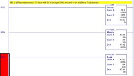
Here is how we do it. N7:0 are the engineering units (Amps), N7:46 is the transmitter full scale (0-100 amps in this case) and the other registers are intermediate calculation results. By the way, I avoid the MicroLogix 1000 for this and many otehr reasons. The 1200 is a better value, and if you throw in the aggravation factor may even be less expensive!

scaling1.jpg
 
Thanks Tom I really appreciate your help, but could you possibly explain your source b in all of the instructions. I have learned it is better to assume nothing.

Thanks again
 
Sure John.

Rung 13: A is the raw data read at the input channel. B is the "zero signal" data determined by test. My experience with the analog inputs on all the MicroLogix is that they are not very accurate (just precise with 15 bit resolution!). So, I use my simulator to find the approximate data value at 4 mA input, and plug that in for data at zero process variable. In this case at 4 mA I apparently measured 6290 instead of the theoretical 6241.

Rung 14: The 100 is a constant for scaling, and will stay the same for any application.

Rung 15: 264 Is the difference between the max data and the min data divided by 100. In my case at 20 mA I apparently got somnething like 32,690 data. (32,690 - 6,290) / 100 = 264

After you get it programmed, be sure to use your 4-20 mA simulator and check 4, 12 and 20 mA results.
 
Last edited:
Thanks again Tom, I got it working perfectly. I did not do it exactly as you did but it works great. As soon as I figure out how to attach an image like you did from RSL, I will post a screen shot.

Thanks again
 
Glad to be of assistance - email me a virtual beer and we'll call it even!

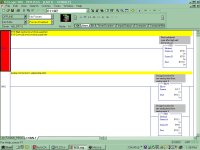
I posted these shots by using Ctrl-Print Screen to copy the RS-Logix screen, then pasting it into a graphics editor like Paint or whatever, then cropping the excess stuff, saving it as a jpg file, and attaching with the Attach file funtion on this site. I'm sure there are better ways, but this is easy, fairly fast, anyone can see it even if they don'thave RS-Logix, and I know how to do it!
 
Maybe stupid question...

Tom,

What is a 4-20 mA simulator?

Bob O.
 
Last edited:

Similar Topics

I need some help with scaling an analog input in an MicroLogix 1000 PLC with Analig IO. Its model # 1761-L20AWA-5A. I have more of these...
Replies
2
Views
6,074
Hi friends, I need communication cable PIN CONFIGURATIONS of AB micrologix 1000 analog PLC with PC. I'm willing to create new cable in my hand...
Replies
2
Views
2,317
Hello all. I have a problem trying to read 4-20mA into a Micrologix 1000 Analog PLC. Not sure if my issue is with wiring, or an option within the...
Replies
7
Views
3,488
Here's a tricky problem: I've just finished a program on a micrologix 1000 using a windows 2000 machine, and logix 500 at the house. When I got to...
Replies
6
Views
4,411
Hello friends I am very grateful for the help my post. now I need to regulate output analog 0-10v, with a sliders Rsview32 thank you joel...
Replies
0
Views
1,451
Back
Top Bottom