Poweflex 4M to Micrologix 1100

rQx

Lifetime Supporting Member
Join Date
Oct 2010
Location
Trelleborg
Posts
1,051
Hi!

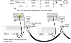
I'm using the 1763-nc01 and AK-U0-RJ45-TB2P to connect these devices. I've tried to find manuals for these but wherent so succesfull. I dont know how to explain it in english but I want to know what output there is from the RJ45 contact on the Powerflex so that I can use the proper colors on my wiring. Is it 24VDC, 24VAC, OHM, etc etc. Thankfull for any help /Tim
 
The DSI port has only Data A and Data B, if you are connecting it to a MicroLogix 1100 and 1763-NC01 cable.

As far as I know there are no color code standards for RS-485. A typical twisted-pair data cable will use EIA/TIA colors like orange/orange-white, brown/brown-white, or green/green-white. Choose one of those and it's likely that your data connection will be recognized as a data connection and not mistaken for DC power or discrete I/O.
 
Hi Tim,

Doesn't answer your question, but i've attached a couple of documents for your information...

As Ken pointed out, the output from the PF4M is an RS485 2-wire, Modbus communication connection. I'm not aware of any (rigid) specification regarding cable colouring here, but you may have local or specific client specs you need to comply with.

Hope this helps.


Regards,

Rob
 
Thansk alot for the answers, I needed to know because we have colors specified on our drawings what to use. I just wanted to know so that it wasnt 24vdc 24vac or something like that, in that case I had to use the colors. Now since it's data I just pick a color and specify what that color is used for.

Thanks alot for the documents, I've been searching for the documents that state how to wire the 1763-nc01. It was already drawn by me in the drawing but it was some time ago and I din't know where I found it. I also have a conection at COM SHIELD to terminal16 on the Powerflex4M and from there to ground.
 
Tim,

The only other thing i would mention is a slight issue we have found when following the suggested wiring scheme (see yellow highlight in first pic)

When the link between pin 4 and ground is present, we experienced regular issues with loss of comms over modbus when the motor reached full [SET] frequency...

We have found other documents (can't easily loacate just now) that do not show this link at all - just a heads up in case you experience any issues when you come to commission your system! (the secod pic shows how we have connected the PF4M previously)

Hope this helps.

Rob

2012-03-04_153012.jpg 2012-03-04_140426.jpg
 
Thanks for that tip! We dont use the wire between pin4 and ground so that wont be a problem for us, thanks for the warning though =)
 

Similar Topics

We have approx 100 PF40 conveyors in our building. Occasionally one stops without a fault being sent to the PLC. We reset/start the conveyor and...
Replies
2
Views
1,389
is it possible to comunicate a powerflex 753 (ccw) using ethernet 20-750-ENETR card to a panelview plus 6 1250 (factorytalk view studio me)...
Replies
0
Views
1,493
I usually access online view of Powerflex by opening the drive module property menu and open the "drive" tab. However, I cannot access the...
Replies
0
Views
1,471
Hi! I have a powerflex 4M frequency driver and a S7 1200 in a control cabinet. My customer wants some times in the PLC to be changed based on the...
Replies
1
Views
1,558
I have been working on this for a while now and I can't seem to get it. I was finally able to view the 1500 on the PanelView under the serial...
Replies
1
Views
79
Back
Top Bottom