Im an idiot at analog?!

joeholick

Member
Join Date
Mar 2012
Location
USofA
Posts
28
Please... for the love of all that is good and evil, help me understand how to program a simple analog program! I have a 10 ohm potentiometer wired in correctly (I believe) between the plus side of the circuit, and the negative is coming straight from a 5v DC power supply. I have my SLC 500 1747 NI-4 set to volts as opposed to current.(how come I can't quite understand the difference between current and voltage??? granted two weeks ago I had no idea what any of this stuff was.)

Second, I have a SCP function in RSLogix 500 that works respectively to the turning of the potentiometer, and it does indeed perform correctly. So basically I understand most of analog and the concept, but my next question is, what can I do in the program next to make those variable numbers trigger something and how do I do it. I have spent many hours looking for help, how-to, and tutorials but I am still scratching my head. Does it involve the move function maybe?? Any help PLEASE!

I have RSLogix 500, a SLC 5/03, 1746 NI4, and one of each ac,dc, inputs and outputs, and one ow16 relay output card.

Could someone please just give me an example of how you could use the variables to trigger different outputs? I think that would really clear things up, especially to see an actual program.

Thanks in advance,
Joe.
 
Hi Joe,

If you're seeing the SCP output doing something, then you've already got all the hard stuff sorted!

In RSlogix500, have a look at the instructions GES, LES, GEQ, GEQ, EQU, NEQ etc. These are all instructions for comparing some numerical value (i.e. not simply a single true / false bit) to some other numerical value. There's good help in RSlogix for these, or you'll find them under "Comparison instructions" in the instruction set manual for the SLC processors, Allen Bradley document 1747-rm001c-en-p

In your case lets assume that pot represents the temperature in the room, and you want to use it to control a fan.

So you'd use a GEQ instruction (Greater Than or Equal To) to test if the scaled value from the pot (temperature) exceeds a setpoint. If it does, then turn an output on to run your fan.

That's a very simplistic example, and you'll see that the "fan" will turn on and off if you adjust the temperature slightly around whatever value you've got in the GEQ comparison. But you can experiment with latching outputs and a LEQ comparison to unlatch the fan run signal in order to make the "fan" run until the temperature drops to another setpoint.

Hopefully that gives you some idea of what you can use analogs for. If you're still stuck, just shout and I can dig out the field laptop out of the truck and write up a few example .RSS files for you.
 
Could someone please just give me an example of how you could use the variables to trigger different outputs?
Joe, Yes, I could, if I only knew what "the variables" are. What address are you using for your SCP output? What range is this output scaled to? It is all about the details, get those right and the rest is easy.

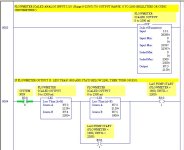
Often is is easiest for beginners to just post their SCP rung of logic. You can do that by printing it to a JPG or PDF file, then uploading and attaching to your next post. In the meantime I will post an old rung of logic using an SCP output to control an On/Off digital output B3:0/1.

SCP Output Example.jpg
 
Last edited:
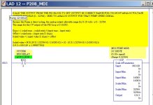
Here is another SCP example with a direct analog output that controls a small pump DC drive.

SCP Analog Output Example.jpg
 
Bernie,

That sounds like the old joke about the new engineer who texted home to mom: "Dear Mom, two weeks ago I didn't know what an injuneer does, now I r one."
 
I think he means the difference between current and voltage inputs (and why you'd select one over the other). Well, I hope so anyway!
 
Thank you for all the explanations. That definitely gives me some idea of how it can be used. I will post a pic of a simple program when I am at that computer again and see if I can't making a fully working program based on an analog input that does something somewhat interesting for an experiment.

I am a 20 year old machinist/CNC programmer and my buddy re-sells PLC gear. He showed me one two weeks ago to help him connect to the computer and go online and such, as I am fairly sharp at anything that involves hardware and software as I was addicted to learning about computers since I they went consumer. When I learned what the PLC did, I had to have one and learn. I am not an electrician by any means, although I am capable of wiring a house from the power pole on, and have a BASIC understanding of electricity, so I apologize if this thread is only for people who have an engineering degree and my questions make most of you cringe or laugh.

As far as current, I understand that as being the amount of electricity that can flow through the conductor. Voltage being the total amount of electricity that is being supplied/generated from whatever source, is this correct? But now, the potentiometer as I view it alters voltage and not the current, (or both WTF?) and so I have the NI4 card set on the voltage setting. How would a wiring diagram look for a current sensing setup on an analog input with say a potentiometer or something easy to understand.

We haven't even got to analog outputs! Just give me a couple examples of where an analog output would be used.

Thank you all, I love this stuff and you are making my life better! Any recommendations on schools to teach you the basics? Or a place to learn everything you need to start working in this field?

Am I getting the kart way before the horse? I USUALLY DO! :)

Joe.
 
hi Joe,

We have voltage / current inputs mainly as each has some pro's and cons.

Voltage inputs are easy to interface to simple stuff (like your potentiometer), but are more prone to common-mode noise and voltage drop over long distances. Even though a voltage input only draws a very small current, the resistance of the sensor cable could mean that 5V at the sensor is only 4.5V at the PLC over a couple hundred metres.

For long distances / noisy environments, current inputs are normally used. These can be zero to 20mA (0.02 Amps) or 4 to 20mA. The benefit of using current for measurement is that the current is of course equal at any point in the loop and is not prone to inaccuracy caused by the resistance of the sensor cable. 4-20mA loops can also be used to supply power to certain low power sensors, i.e. they don't need their own power supply. Very useful for tank level sensors, pressure gauges etc.

See http://en.wikipedia.org/wiki/Current_loop - Process control section for more info and some drawings.

Setting up a 4-20mA input using a pot is a bit more tricky (and would need additional resistors), i'd stick to voltage input for reading pots. But if you do ever have to interface to real world sensors, 4-20mA is in my opinion the way to go.

Analog outputs - can be used for all sorts of things like providing a speed command to Variable Speed Drive for controlling the speed of a centrifugal pump or fan, for example.

As for schools, can't help you there - We learnt next to nothing about PLCs in my university degree in Electrical Engineering (which is a little crazy IMHO) and I have taught myself most of what I know. Having a PLC to play with is a great learning tool, and you can of course use it as its own simulator. For example, I use an old SLC 5/03 to write test applications for another brand of quite basic telemetry units we use that have an Assembly style programming language and no simulator.

I write simple programs in the PLC to simulate a rising water level (which is fed to the telemetry unit through an analog output on the PLC), and the telemetry unit turns on an output to start a pump. This output goes back to the PLC as a digital input, I use this to simulate a pump running to decrease the well level.

Very handy for testing a new pump station switchboard before we deploy it!
 
The basic concept of current and voltage goes like this. A water faucet normally has water pressure behind the valve even when cut off. This represents Voltage. When you open the faucet valve, water flows out. This represents Current. Voltage plus current represents power, or Watts.
With your potentiometer wired as in post 1 it allows the wiper arm to position itself anywhere between the 5 volt point and the 0 volt point.
Therefore your input card, the NI-4, is receiving volts as determined by the wiper position. I hope this helps and doesn't seem too simplistic.
 
Last edited:
Hope these pics are large enough to read. I have it working and beginning to get a better understanding. Next question, what instruction would be used to turn on the output between two set limits? Right now, the way the parameters are scared, the light turns on (O:6/0) when "0" or greater is reached on N:7/0. So I basically scaled the parameters to make the light turn on once the shaft has been rotated about 50 percent of full rotation. How would I have it start up at 20 percent and turn off at 60 percent? I have an idea but would like to know the right way.

Thank you again!

http://flic.kr/p/bp92km - pic of what I am explaining.
a%3E
 
Hi Joe,

One simple way is to add another instruction (LEQ) in series with the GEQ you've got. The logic would then be:

if N7:0 is greater than 20% and N7:0 is less than 60%, then the output must be on.

Another method is to change that OTE output instruction to an OTL. this is a latching instruction, and the output will remain true even if the precending rung conditions go false again. You need to use an output unlatch (OTU) instruction to set the output to false.

To use the latching outputs, you'd have the GEQ instruction latch the output on, and the LEQ unlatch the output.

give that a go!
 
...and the output will remain true even if the precending rung conditions go false again. To use the latching outputs, you'd have the GEQ instruction latch the output on, and the LEQ unlatch the output.

Give that a go!
We learnt next to nothing about PLCs in my university degree in Electrical Engineering....
Joe, please don't start off by using latches - one of the most dangerous methods for a beginner. Instead, use an OTE (the PLC equivalent to a regular old relay coil), with seal-in contacts to keep it on and turn it off. A Latch is the PLC equivalent to a mechanical latching relay, and once it is ON, it takes another Unlatch coil on a separate rung to turn it off. Beginners often forget the Unlatch, or implement it incorrectly, or set up the unlatch logic in a subroutine that is not called, or allow the system to be switched out of RUN mode without UNLATCHING all the latched bits, and so on. Sure, latches have their place and proper use, but beginners should not rely on them!

A PLC latched output can come back on unexpectedly if the power blinks off and then comes back when you have your hand inside the grinder (or cutter, mixer, stamping press, you-fill-in-the-blank with whatever dangerous equipment you will be working on). A sure mark of a poorly-trained programmer is the use of large numbers of PLC latching relays. Usually I see latches used where the programmer does not really understand how to implement other control means. So don't start off by making things more dangerous and difficult than they need to be.
 
Last edited:

Similar Topics

How do I? "LVA_SW1_SPD_REMOTE" "LVB_SW1_SPD_REMOTE" JC If first line is =1 or second line =1 Jump _003: \used to stl
Replies
3
Views
1,368
I'm confused SLC500 is fine I understand, but Controllogix 5000 revision 20. 1756 IFHI8 card how do I scale the input? The input is a dumb analog...
Replies
14
Views
3,881
If you were going to go down to the closest overpass or homeless shelter to hand pick a person to install, program, and tune 1/16DIN panel PID...
Replies
14
Views
5,782
Hi all I'm trying to setup a very basic "live map" of a bussiness park (nothing as fancy as what you guys normally do :)). It is basically a...
Replies
2
Views
1,426
Hi all, I have spent about 3 days after hours searching around the net and I have picked up enough information to order a 3kW 8 pole for an AC...
Replies
30
Views
10,017
Back
Top Bottom