Show me a sample analog output.

joeholick

Member
Join Date
Mar 2012
Location
USofA
Posts
28
Okay, I don't know why I can't figure this out. I have a 2 axis joystick wired into my analog IO card on my SLC5/03 rack (os302 i think). I have scaled my parameters and have made little sample programs with outputs turning on at set limits and what not, but how the heck do I wire and program the analog output side of things?! I have motors, leds, batteries, resistors, whatever! I just need someone to show me how you vary an analog output, with regards to what the analog input is reading. I have searched and searched but I just need a sample program to learn by.

Thanks everyone.
Joe.
 
Making things a little more clear: I have a potentiometer wired to an analog input; can someone please explain how to wire and program something such as a small light bulb or motor coming from the analog output. I just want to see the light get brighter or dimmer, or the motor speed up or slow down.

RSLogix500
SLC5/03
1746 NIO4I
 
Choose a 10 KOhm potentiometer.
Within RSLogix 500 project file, MOV 32767 to NIO4I OUT Channel 0(this will give you the 10 vdc reference for your potentiometer); wire up the pot to OUT Channel 0. Wire up the pot "wiper" to IN Channel 0. Wire up a 12 vdc LED to OUT Channel 1.
Within the project file, MOV IN Channel 0 value to OUT Channel 1.
Increasing/reducing the resistance of the IN Channel 0 circuitry will directly and proportionally vary the value of the OUT Channel 1 voltage output which, reciprocally, will vary the LED's light emission intensity.
 
Last edited:
To control a motor, you will need to use a drive. You can send your output signal (be it 0-10V or 4-20mA) from your output card and wire it to the input on your drive. Your drive will then use this signal to speed up/slow down your motor.
 
You lost me dmargineau... so the pot has to be wired to an output also?!?

As far as the motor drive, my friend has a bunch of them but they all look like they are for huge cnc machinery. I just want to turn a small hobby servo motor that fits in the palm of my hand. What method for that route?
 
I'm sorry, maybe a little more detail will help!:)
You will have to "give" a reference voltage to the potentiometer(the ends of the potentiometer windings will need a voltage applied to it). So if you have an Analog combo voltage module module(http://literature.rockwellautomation.com/idc/groups/literature/documents/um/1746-um005_-en-p.pdf- Pg. 3-13), writing 32767 to an OUT voltage channel will generate a 10 vdc voltage between the channel's V and RET terminals.
This voltage could be applied to the pot's windings as the reference to be "trimmed" by turning the variable resistor's knob. The pot's "wiper" will be then read as a voltage analog input, which's value could be directly written (via RSLogix MOV instruction) to a voltage analog output, which will be directly proportional in magnitude to the voltage value generated by the potentiometer's trim.
 
Last edited:
Joe, The issue has got confused. Let us start over. Here is your best summary of what you need:
I have a potentiometer wired to an analog input; can someone please explain how to wire and program something such as a small light bulb or motor coming from the analog output.
Your best answer so far (for the wiring):
Wire up a 12 vdc LED to OUTput Channel 1.
I don't see that you have received ANY answer about how to program something like a small light bulb to work from a 1746 NIO4I analog input, through the program logic, to power an analog current output.

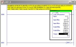
Basically, use the SCP command to (1) scale your input to the same range as the analog output, and (2) move the new scaled value to your analog current output.

It seems that you really need a Voltage In, Voltage Out module (instead of your Current In, Current Out module) to use a pot voltage-changing device and a LED voltage-sensitive device.

JOE'S ANALOG IN TO ANALOG OUT.jpg
 
Last edited:
Joe,

The SCP will take care of the IN and OUT, but you have the problem of how to interface your voltage-varying pot with a milliamp current-varying input on your 1746-NIO4I. Now if you have a 1746-NIO4V, you could connect your pot directly. Without that, you will need to make sure that your pot (or a pot & resistor combination) produces a current output ranging from 0 to 20 or 4 to 20 mA to feed the 1746-NIO4I. For a 24 VDC supply voltage, the pot range should be 1200 to 6000 ohms to produce 4 to 20 mA. You could use a 1.2 kOhm resistor in series with a 0-to-5 kOhm pot.
 
Last edited:
Joe,

I screwed up (or down). The 1746-NIO4I can be selected to have either current or voltage inputs, so you can set it for voltage (ranging from -10 to +10 VDC), but only current outputs are available on this module.
 

Similar Topics

As the title says, I'm using CCW with a PV800 (and Micro850). I've made a scheduler in which a user can choose a month, day (1-31), hour (0-23)...
Replies
15
Views
500
Please help me, I have solve many week but still not solve it. I found trouble of factory talk studio when I set tag by browse address of OPC...
Replies
0
Views
117
Hi All, I'd like to know how to show 100 days of Alarm in the Alarm Summary in Aveva (Intouch) SCADA. I couldn't find any option like that in...
Replies
10
Views
826
If I have a PanelView Plus, is it possible to show historical data via historian on it? I have the application all setup in FT Studio Machine...
Replies
3
Views
484
Migrating v8 FT View SE to v13, had to export tags because after v10 the configuration is no longer supported. Imported tags to new Tag Alarm...
Replies
1
Views
503
Back
Top Bottom