hi to all!
I have been an Equipment engineer for a year at my past job and turned instrumentation engineer in my current job. I have been learning to program a lot of PLC models on my own (mitsubishi, panasonic, omron, keyence, schneider).The latest PLC model that i have been learning is allen bradley. my knowledge on PLC programming is limited only from basic to advanced DIGITAL controls and HMI programming. I have no idea on how to program neigh to wire an analog intrument to a PLC. I graduated 2 years ago as an electronics and communications engineer so I have not been taught in school about PLCs. I didnt even imagine that there was a technology like this since my first job.
Please help me understand analog controls. specially the wiring schemes.
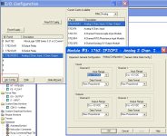
We have an upcomming project using an allen bradley PLC. I have been in tune with advanced instructions of the PLC for the past week so i can minimize my program ladders. i have been fiddling with AB micrologix 1200 with 1762-IF20f2 analog expansion module on channel 3. i understand that it has two output words O3.0 and O3.1 for voltage(0-10VDC) and current(4-20mA) outputs. but which is which? is 3.0 fo current?voltage? and 3.1 for voltage?current? Also, input wise, why are there 6 channel words that are created? I:3.0, I:3.1, I:3.2, I:3.3, I:3.4, I:3.5? what are those for?
I hope i could get enlighten on this one. thanks!
Jomar


