Can someone help me with the batch simulator?

Grachy

Member
Join Date
Apr 2012
Location
Florida
Posts
2
Hi, I have this homework about batch mix simulation, for this I have to set switch A for single batch and switch B for continuous operation. Until know I have the program for a single batch but I don't know how to make multiple batches. The following instructions are the ones I am missing:

- When the selector switch is in position B, the system will be able to produce multiple batches. The number of batches produced will be determined by the user using the control panel thumb wheel switches.
-The operator will be able to specify the product ratio by entering the desired product one percentage using the control panel thumb wheel switches.

I will appreciate your help. Thanks :)

Please see the attached files
 
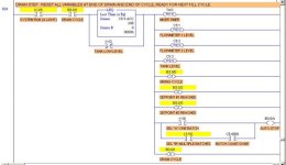
Yes, here is a hint. Notice the selector switch contacts at the bottom of Run 024 (the last rung in my program) that control the Auto-Stop relay. You can probably find other help in the "Downloads" section.

Batch Mix- Selector Switches.jpg
 
Last edited:
Thank you... Sorry for the questions but I new with the program... What is B3:0/4? And if put as inputs Switch A and B do I have to program those first, or not?
 
B3:0/4 is a PLC internal relay that I defined and set up as "AUTO STOP" to perform the function of stopping the cycle at the proper time (whether it is running in "A" single-cycle, or "B" multiple cycles controlled by Batch Counter C5:4).

And if put as inputs Switch A and B do I have to program those first, or not?
I am not sure that I understand your question. Did you mean, "If I use I:1/9 and I:1/10 as Selector Switch A and B inputs, do I have to define them first?"

Well, yes and no. The LogixPro creator Bill Simpson (who hangs out here sometimes) set up those two inputs for you, but you do need to add the labels (symbol descriptions) so that YOU will know what they mean. LogixPro already knows. Hover your mouse pointer over the "A, B, and C" of the Selector Switch in the Simulations control panel, and you will see where the Inputs for these switch contacts are alredy tied.

You can see in the picture above of my running program, that the Selector Switch is set for "B" and that I:1/10 is ON (highlighted in yellow), and that the current Drain Cycle has finished, but that the Batch Counter has not yet reached its number of batches, so AUTO-STOP has not been triggered on this Fill-Mix-and-Drain cycle.
 
Last edited:

Similar Topics

If a programmable controller controls the operation of a motor, what connects motor control to the PC? A) Line voltage B) I/O device C) Modem D)...
Replies
27
Views
7,080
Hi all, Am new here, normally I work on OSAI and Beckhoff systems but I have a problem with some Indramat dkc11.3 drives that all display the...
Replies
1
Views
1,420
i have a project that i need help designing. i go to college but we only get 2 hours a week to work on the computer that has the plc program. i...
Replies
8
Views
2,407
Hi, i uploaded program from Allen Bradley PLC, i need someone to help me elaborate more on this uploaded project will appreciate any help thanks
Replies
6
Views
2,107
Hi Friends ! I'm having a little challenge here, I'm almost done in my conversion project from panelBuilder to Factory Talk. I really need a...
Replies
0
Views
1,546
Back
Top Bottom