PLC-5 30, 1771-IFE/C manual configuration

mphymel

Member
Join Date
May 2005
Location
SE Louisiana
Posts
4
Guys, I am having problems setting up an analog in module. The PLC is existing, and has two 16 slot chassis. Single slot addressing. My new module will be in rack 3 group 2.

The remote chassis contains a 1771-ASB.

I cannot access the IO configuration dialog, when I do, it does not appear that this was ever set up. Is this possible?
The IO config dialog box come up with the scanner radio button selected.

I thought I could add my new module without using this dialog, but I have not done this a over 8 years.

Here is where I am. I have the BTR and BTW set up with the enable bits and the first scan bit for the BTW, like the manual says. I will be differential 4-20ma. My data lengths in my BT instructions are set to 22 for the BTR and 39 for the BTW. These are probably more than I need. Let me know if they must change.

My data in the config N: file is set to 500H for word 3 of the config word, and my min & max range registers are set to 0 & 4095 respectively.

  • I am not sure if my BTR and BTW have the appropriate Rack/Group/Slot settings. They are set to 3,2,0 which coorresponds to the location that the module is installed. was this supposed to be the remote IO adapter RGS or the actual card RGS settings like I have?
  • One odd thing I saw, is that the BT control file records do not have any data in them. Is this normal?
  • I also have the ER coil active on the BTW, and no status bits set in the status word of my data file for the BTR.
Any help would be appreciated.
Mark
 
I cannot access the IO configuration dialog, when I do, it does not appear that this was ever set up. Is this possible?

Yes, PLC5s do not require I/O configuration. Its for documentation only, very helpful if it's there though.

The word length of 22 and 39 are correct.

What slot is the module in?
Can you post the .RSP file ( zip it first)?
 
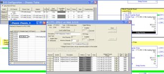
Using your file I added the card to the I/O configuration. That is the easy way to do it. See
picture below.
You need to add the remote chassis to the I/O configuration then add the module to the chassis, it will ask you if the BTR/BTW exists just say yes.

Is the module in the slot shown in the picture? If not then you will need to change the Rack/Group/Module settings.

Also check and double check the jumpers on the card to make sure they are where you want them to be.

Also the rogram (file ) you posted shows 3 remote I/O racks? Which one is the new card in?

What is the size of the chassis with the processor and the size of the remote I/O chassis?

addcard.jpg
 
Last edited:
Mickey,
First let me thank you for your help. I ended up setting up the IO config for both chassis, they will need that, and it was not that painful, I noticed the PLC5 software recognizes the points associated by address.

I configured the analog module with the config utility, and I deleted my BT instructions, and let it re-create them, as well as overwrite the data. It made the same data settings that I had, but it also properly set up the BT records, which I did not do.

I still have an error bit on the BTW, but no error bits in the BTR status register. Originally the jumpers were not set, and I knew they would need to be, so I took care of that, but still the error bit. Furthermore I set a value in the first analog data register, and it did not get overwritten.

I will be back out there to work on it some more.

PS, could the Rack 4 you asked about be a panelview device? The existing program has a bunch of panelview BT instructions that refer to Rack 4.
 
PS, could the Rack 4 you asked about be a panelview device? The existing program has a bunch of panelview BT instructions that refer to Rack 4.

Yes, if your PV supports RIO protocol.

Are you sure about the slot # to card is in. Remember the first slot in PLC5 chassis's has no number, it's for a processor or a RIO adapter. Sorry if this sounds basic, but thought I would mention it anyway.

Tell us how you set up the jumpers and post your new program and maybe someone can spot something.

BTW, the program you sent is password protected.
 
Last edited:

Similar Topics

Urgent!! Hi all I am a newbie here. Currently I am migrating from plc-5 to controlLogix. When 1771-IFE change to 1756-IF16, I am getting a...
Replies
4
Views
2,376
My question is, when there is 10V on the first channel of an 1771-IFE card, what decimal value will show up in the data file word (happens to be...
Replies
15
Views
6,078
I have a tonnage monitor module hooked up to an analog card using a plc 5-30. Analog Card is a 1771 IFE/C. We had the OEM visit to do calibration...
Replies
4
Views
1,739
I need to add an analog input to this legacy plc 2/17 system. I placed the module in the very last slot of an 8 slot chassi, next to an on board...
Replies
9
Views
1,923
Hi, currently have an series A IFE module in PLC 5 chassis. Running fine for years. Last week starting getting erratic data from all channels...
Replies
8
Views
2,336
Back
Top Bottom