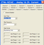
using 1746-NI16I

jkCBWPnet

Member
Join Date
May 2012
Location
PA
Posts
17
I have searched a bit and studied the users guide and I think I am close, but I must be missing something stupid. This is my first PLC experience. I have a slc500 with 5/05 processor using rslogix500 and rslinx oem. I am trying to get an OPC bridge setup. This is what I have so far.

I copied the program from the user book on pages 97-98 of the guide. (except my card is in slot 3 not 6)http://literature.rockwellautomation.com/idc/groups/literature/documents/um/1746-um001_-en-p.pdf
I went in i/o configuration saw the card listed and went to adv config, specified 4-20mA and just kept the default 6hz and other settings. I kept it at engineering units as I am not sure what to do with it yet. (It can be manipulated by the receiving program anyways I believe)
I told N7 to allocate 100 words/bytes (not sure what those units are)
I downloaded that ladder file to the plc

Does the ladder program loop? is it one shot for "configuration" like it says and I need something else to keep the data current?

What do I need to do so I can see data representing what I have on the inputs to the card?
input 0 is from a 0-1200cfh nitrogen flow meter via 4-20mA
the rest (1-15) are just connected to common as per install intructions at the moment.
 
Did you power the SLC5/05 down, or take it to program then back to run, so that the configuration gets written to the card on the first pass of the program on restart.
 
Post your .RSS file ( zip it first).

If your card is in slot 3 then the raw data will show up in the I:3.0 thru I:3.15 ( see picture below). You can then use the "SCP" instruction to scale your raw data to engineering units.

data.jpg
 
it was in rem still. I put it in run and run light came on. still no data. here is rss file...

that is where I expected raw data. it is all 0s and I ran input through it's span.
 
It was alright for it to be in REM, what I was asking is, did you take it to Program then back to Run, as this makes the first pass bit active for one scan and writes the Configuration file to the card.

Mickey showed you the file for I:3.x
What values do you show in O:3.x
as they are the card configuration file.
 
The file you posted shows... see picture. You need to enable the channels.

Go online and save the file while online, then post that. After you double check the card's configuration and do as Gil47 says.

postedfile.png
 
every time I went into that adv config it showed the same default values. As if hitting apply/ok did nothing. I will be back to work tomorrow 7am EST
Sorry I'm such a noob ;)
 
every time I went into that adv config it showed the same default values. As if hitting apply/ok did nothing. I will be back to work tomorrow 7am EST
Sorry I'm such a noob ;)


Did you save the program after you changed the configuration?
 
your board lost my post. ok I will make this shorter. There is data at I:3.0 when I ran span of input. I did not see a change at N7 does this ladder loop or is it one shot? N7:46 13, 14, 15 are green but N7:47 13, 14 and on are not. The lights for input status on the card are flashing, this seems wrong. All inputs besides the first (0) are tied to common as per instructions. is this the reason maybe? Do I need to add a looping comand to get data to N7? I believe that is where my opc bridge is looking for data.

05292012_ss01.bmp
 
every time I went into that adv config it showed the same default values. As if hitting apply/ok did nothing. I will be back to work tomorrow 7am EST
Sorry I'm such a noob ;)

I have not used the 16 channel version but I suspect it is the same as many of the others. When you use the advanced config to set up the channels, and apply them a rung is created with a new data table which will perform a copy from a new data table of all the pertinent data in order to configure the card. If you apply the changes (offline) the tickbox for enable will determine whether bit 15 is set for each channel. Once online, I don't think you can apply changes.

You can, however, go into the source data and set the bits manually. I normally provide a user bit in parallel with the first scan bit so I can make changes to the configuration while in run mode. I just toggle the bit on and turn it back off.

I normally use the advanced configuration when I am adding something new, but then I go in and comment all the bits for the config data, so I can make changes later without having to RTFM.
 
Incase you are just catching up, ;) I know very little about these components and dont know where the source data is, how to set bits manually, and basically don't know what your last 2 paragraphs mean.

Lets not worry about N7:47 or later unless it matters. N7:46 is for input 0 and that is all I need to monitor atm.

I seem to have data at I:3 what do I need to do to get it to N7

data value bits from the Data Files I1 - INPUT on line I:3.0 change as I move the physical meter from 0 to span.

data on N7:0 does not...
 
yes one channel at the moment. does this ladder program loop or is it one shot (refer to previous posts)

I looked at the program again and it seems as if rung 2 does the exact thing you mention (I just copied this code from the user guide and changed their I:6.0 to my I:3.0 but I see that rung 2 has the value moved to N7:30 instead of 0. That may not matter (maybe I just needed to know where to look for my data.)
I will tell opc bridge to look at N7:30 instead of N7:0

does that make sense? Am I on the right track? I guess I could have simplified this more for only 1 input, I was just hoping this way I would only have to program the plc once until I add more cards...
 
The raw data from your input card is in I:3.0 thru I:3.15.

N7:0 thru N7:15 are the configuration words which get written to O:3.0 - O:3.15 on first scan of the processor, they do not change unless you make a configuration change to the card.

But we really need to see the rest of the program, post it if you can.

INPUT on line I:3.0 change as I move the physical meter from 0 to span.

If that is the case then the card is working.

You can now scale the raw data to engineering units to suit your process. Tell us how you have the card configure and the engineering units you want or post the program ( zip it frist) and someone will give you an example of a "SCP" instruction.
 
Last edited:
Does the ladder program loop?
Yes.
Is it one shot for "configuration" like it says?
Yes, because your sample program uses a special Status bit S:1/15, which is ON for only ONE PLC scan when the PLC program runs for the first time (when the PLC is switched from PROGRAM mode to RUN mode).

. . .and I need something else to keep the data current?
Your data at Input I:3.0 will always be current if that Input module is enabled and the PLC is in RUN mode. Now, if you MOVE or COPY that input data somewhere else, such as N7:46 as you have done, it will only be current when that rung is active. In your case, you are trying to use the results in the last 3 bits of N7:46 (bits 13, 14, and 15) to determine when or if you move something INTO that SAME 16-bit word N7:46. That is a no-no, a conundrum, a dog chasing its tail and will not work. As soon as one of those bits = 0, then nothing else will get moved - ever!

Example: Your logic would be like saying "If the value of N7:46 = -8192, then move the value in I:3.0 to N7:46 (thus changing the value of N7:46, maybe making N7:46 not equal to -8192, so no other MOVEs will ever be done).

Now, if for some reason you only want to move I:3.0 WHEN the last 3 bits are = 1, then you could use I:3.0/13, I:3.0/14, and I:3.0/15 to enable a MOV. But most of the time, if you want to look at the value of an analog input, you need to look at the entire word, not just 3 bits.
 
Last edited:

Similar Topics

I am looking to replace a SLC5/05 processor with an AENTR adapter. Configured the rack in a compactlogix. The connection to all of the cards in...
Replies
5
Views
2,310
Hello, We have an older SLC500 controlled system that is using a BASIC module to communicate to a third party device. Looking into converting the...
Replies
4
Views
1,276
Hello Upgrading to a ControlLogix processor using existing 1746 I/O (If it ain't broke why fix it?) Main Rack 0 - 13 Slot Chassis Expansion...
Replies
4
Views
2,679
Hi guys, I'd like to to ask I can use the 1746-IB16 with a rotary encoder from Omron E6B2-CWZ62. It's just for a training kit, I do not...
Replies
3
Views
2,032
I am running into a problem with the 1746-HSTP1 Stepper Controller Module for my SLC5/03. I am trying to get the stepper motor to just jog. I dont...
Replies
1
Views
2,533
Back
Top Bottom