robw53
Member
i have got setup in the shop a 1400 with a 1763-nc01 adpator to allow me to talk MODBUS to the drive. so far i have setup both the drive and 1400 as follows:
MODBUS MASTER (PLC)
9600 (AND ALSO TRIED 19200)
NONE
1
8
drive set as node 1
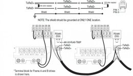
for the wiring i am using 1 twisted pair and a drain wire, i have read that you need 2 pairs and use one of the pairs as a common but i have also seen and read just using 1 pair, which is how it shows in the drive manual for the PF40 so anyway i have the setup as the following:
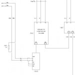
on the NC01 i have A and B connected to the pair and the drain wire connected to ground on the block, on the drive end i have the RJ45 screw plugs for pins 4&5 and connected these up to each wire, the drain i have tried connecting to PE and also in the drive manual it says try connecting this to terminal 4 which is the network common, but to no avail, i have the resistors fitted at both ends and tried various wiring setups as per the manuals, what im really struggling with i believe is to be the correct wiring for the NC01 as i crnt find proper wiring diagram for this.
when i tried send a message:
Ch0, Modbus command 03, N10:0, 1 element, 16 bits
target device:
msg timeout 2
modbus address 8449
node 1
all i get is a fault (HEX)37 message timed out in local processor
any help would be greatly appreciated
Rob


