Can a faulty modutrol motor damage an analog o/p module - sm 332

dasrajib

Member
Join Date
Jun 2012
Location
New Delhi- India
Posts
3
Dear All
We are using Honeywell make Modutrol Motor (Model- M7284C1000) in our Burner system. The Modutrol Motor is acting as a damper actuator, it has been controlled by 4-20 mA which is outputted by Analog O/P Module( Model - SM 332). We are using CPU S7-300.

We are recently facing problem in this system for few of our customers.
Problem: We are observing that whenever these Modutrol Motors become faulty like the modutrol motor stopped working on getting the mA supply from the Analog O/P Module, after a few days of time the Analog O/P Module started showing 'SF' error LED ON and then we did not get the mA output from the Module from any of the 8 channels.

We have observed that:

I. For faulty Motor, the resistance between ‘+’ and ‘ – ‘ in the Terminal board of Motor is somewhere between ~ 5.1KOhm to ~ 56 KOhm.

II. For OK motor, the resistance between ‘+’ and ‘ – ‘ is somewhere between ~101Ohm and 120 Ohm.

My question is:

In the present connection system of Analog O/P Module and Modutrol Motor, if Modutrol motor is faulty, can it also make Analog O/P module faulty? - which is happening for few of our customers.
We have thoroughly checked all the connecting cables- found OK.

Thanks and Regards
Rajib L Das.
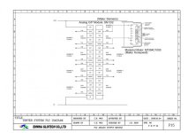
Analog output Module - Modutrol Motor.jpg
 
You have problems with 0 Volt thus grounding.
the card is not isolated, and the motors are also not isolated, so a lot of voltages are present in your system, burning the input circuit of the motor.
 
A three way isolator will solve the problem. That is an isolator that provides isolation between all of the connections: INPUT, OUTPUT and POWER SUPPLY.
There are many manufacturers of such, one is Weidmuller.

A better solution we have used for many hundreds of similar motors in India and many other countries is to use two digital outputs to drive the motor with INCREASE and DECREASE and use an analogue input to measure the motor position from its slidewire.
 
Clips from the SM332 analog output card manual are here:

2efoq9t.jpg

A current output is always rated to be able to drive its maximum current through some specified maximum resistance, in this case a maximum of 500 ohms. But industrial outputs don't die when there's a greater resistance. The greater resistance limits the current (to whatever 18Vdc can drive) but the higher resistance doesn't kill the current driver. Usually. I would expect the output to source between 0.3mA and 3.5mA (18V/56Kohm to 18V/5.1Kohm) and not over heat and die.

If a high resistance load is a problem for the Siemens AO's, can the wire break detection be used to alarm on high resistance? I can't find where it states what the detection technique is, but maybe wire break goes to a fault state for this situation.

But, there's a spec for inductive loads. Presumably the 4-20mA never 'sees' the motor winding coils and I'm clueles as to the inductance of a Modutrol motor. But the nature of DC seeing little reactance through a copper winding makes me wonder if the failure mode somehow allow the current signal into the motor winding circuit. I wouldn't think so, and a relatively high resistance for a failed input suggests that a motor coil is not part of the circuit.

What Siemens calls 'Insulation' I would call 'isolation'. The lack of isolation channel-to-channel infers that what happens on the common ground on one channel can happen on other channels. Is it possible that there are significant common mode differences between motor

Paul, how do you know that the actuator's motor 4-20mA input circuit is not isolated? Aren't the motor windings driven through relay contacts?

John, is the reason for position proportional drive to avoid ground issues with 4-20 control signals?

One alternative you should know about are 'valve position' converter modules. These API brand units plug into 'octal sockets', frequently used for plug-in electromechanical relays. Their function is to convert the 5-20mA control signal to a drive clockwise (CW)/drive counter clockwise (CCW) or hold position, using feedback signal from the motor to determine when the position is reached.
http://www.api-usa.com/valve_positioner.php

The M7284 is a 150 inch pound torque, non-spring return, 4-20ma input, 2 auxiliary switches, dual ended shaft

The M9184 C/Q/F would be an equivalent drive CW/drive CCW with slide wire feedback.
 
Link to Honeywell Modutrol motor data sheet
http://controls.acmecontrols.com/Asset/M7284C-1000.pdf


Page 9 shows the wiring for the motor
and for multiple motors.

Note that each motor needs to be fed by its own transformer
Motors should not share the same power supply.

These are just some of my thoughts on what maybe your problem
as my dealing with these motors has normally found them to be quite robust.
 
Last edited:
Isolation may be solution

Dear All

My question to you all why Siemens didn't mention about the isolation in the datasheet for SM 332 Analog o/p module.

I am trying to insert some kind of isolation between the source and sink and will let you know the results.

Thanks all.
 
danw,
I use 2 Digital outputs (with opto isolators) and an
analogue input from the motor slidewire for improved valve positioning.

If I ever have to use 4-20mA output or input I use a three way isolator.

I pay particular attention to grounding and separate all field wiring into separate ducts for A.C., 24 Volts, and low level signals such as thermocouples.
 
I think what DanW specifically explained, is that 4-20mA outputs can be opened or shorted without damaging them in most cases. You can't however, attach 120 volts to them when reconnecting a Modutrol motor as has been the case for me in a very similar application on a SLC.

When the 3rd channel died in about 6 months time, I finally laid eyes on the reason...all wiring for the motor and for the 4-20ma signal to hte positioner board, was wire nutted in a 2 x 4 box deep inside a dark cramped enclosure on the roof of our plant. I think there was another 120v switch landed in that little box too. It was too easy to arc them together when halfass-manship was required ... I pulled a new 4-20mA braided shielded cable via different route and haven't lost another analog card. We have probably a dozen or more of the modutrols (older model) with positioner board and we lose a positioner board on one them at least a couple of time per year. I chalk that up to electrial disturbance (specifically, thunderstorms and lightning)...
 

Similar Topics

Hi, Need help with coding for a faulty component sensor which we are using a push button as we are using a test rig. the plc is a allen bradley...
Replies
4
Views
205
Hi, i have a PLC B&R X20 CP3484. The machine was shutdown for months due to which I got to loose the plc battery, in the same time ethernet...
Replies
1
Views
113
I am providing 24 volts on encoder input but getting the 24 volts on encoder output.The output voltage is not changing,so I want to ask what will...
Replies
4
Views
2,342
This is a sort of research question. A small motor burned out (3KW) the bearings seized and took out the windings, that plus multiple resetting...
Replies
8
Views
2,277
im a noob in need can someone help make a ladder logic system that can stop the production line when there is a faulty bottle, and two pneumatic...
Replies
6
Views
1,426
Back
Top Bottom