Help Dual compressor [Logixpro]

Welcome to the forum!
Do you need help on how to use LogixPro or help doing the Air Compressor Exercise? If you need an example file for the Air Compressor program, try the Downloads section, under Allen_Bradley.
 
Gato,

The YouTube version of the LogixPro Dual Compressor simulator (from "mecatronique") is correct for Student Exercises 1 and 2. However, for Exercises 3 and 4, it will not work very well.

You will have to make modifications for the last two more advanced exercises. You will need to add two Subroutines to the YouTube program in order to complete Exercises 3 and 4. In the YouTube demonstration, the Selector Switch that should display the accumulated running times for Compressor 1, Compressor 2, or Both, was not programmed.
 
Last edited:
Friends need this:
Automate the process requires dual compressor whose requirements are:

a) Mode A: the two engines running at the same time with 50% flow. Consider a range of pressure to both ends of the pool of 30-100 (psi). When it comes to 100 (psi), the engines are stopped and the pressure begins to decrease to a minimum of 30 (psi).

b) Mode B: the engine 1 to work for a certain range of pressure and the motor 2 start work for another range.

c) Mode C: run a single motor.

The lights should come on board: C1, C2 and run as appropriate and start and stop buttons should work without problems, for modes A, B and C. Find out how the box% FLOW influence the process and carry out a program where they see their operation and influence.

In Spanish

[FONT=Arial,Arial][FONT=Arial,Arial]Se requiere automatizar el proceso de compresor dual, cuyos requerimientos son los siguientes: [/FONT]

[FONT=Arial,Arial]a) Modo A: los dos motores funcionan al mismo tiempo con 50% flow. Considere un rango de presión para ambos extremos del estanque de 30-100 (psi). Cuando se llegue a 100 (psi), los motores se detienen y comienza a disminuir la presión hasta el mínimo de 30 (psi). [/FONT]

[FONT=Arial,Arial]b) Modo B: el motor 1 funcione para un cierto rango de presión y el motor 2 comience a funcionar para otro rango. [/FONT]
[FONT=Arial,Arial] [/FONT]
[FONT=Arial,Arial]c) Modo C: funcione un solo motor. [/FONT]

[FONT=Arial,Arial]Las luces del tablero deben encenderse: C1, C2 y run cuando corresponda y los botones de partida y parada deben funcionar sin ningún problema, para los modos A, B y C. [/FONT]
[FONT=Arial,Arial]Averigüe cómo influye el recuadro %FLOW al proceso y realice un programa en donde se vea su funcionamiento e influencia. [/FONT]

[/FONT]Is a report that I do for school, please who can help me develop this exercise? Thank you.
 
Last edited:
Gato,

I can help you develop this exercise. Let use start with Mode A. What have you got so far? Do you have any rungs of Logixpro written that we can start with? If so, please ZIP them and post as an here. Also, In LogixPro, you can "Print Rungs as Picture" and post it as a *.jpg picture file.

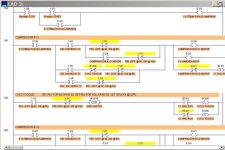
Here, I will get you started with an outline of the required OUTPUTS. The outputs are the instructions that perform the actions, therefore should be programmed first to use as an outline for your program.

Now, what instructions (switch inputs and relay contacts) need to be added to each rung to complete each action?

DUAL COMPRESSORS MODE A.jpg
 
Last edited:
Now you have more than nothing. Type in the program that I posted, and you will have a place to start.

Okay, maybe you have not learned to type yet. Here is the basic LogixPro Outline that I posted.

TIPS: Mode A, Set PE1 Setpoint = 70 psi, Span = 40.
Mode A, Set PE2 Setpoint = 100, Span = 40.
Use both PE1 and PE2 Pressure Switches in series to control each compressor motor output.
 
Last edited:
Here I have the dual compressor program developed

this correct?

also need to explain how it works
 
Last edited:
Gato,

You got off track a little and did not use the outline that I posted for you. Also, you used some Inputs (I:0/0 on Rung 000, I:0/1 on Rung 003) as OUTPUTs. Those will not work very well. Try this method in the attached files.

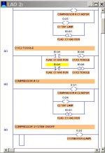
Explain how it works: For Modo B, you need a Flag bit that shows if Compressor 1 has RUN, or not. Rung 002 creates bit B3:0/0 "C1 or C2 TOGGLE". Rung 002 must be located in the program BEFORE Rung 003 or it will not work correctly. B3:0/0 is turned on when Compressor #1 has run and the pressure switch PE1 is turned ON. This allows Compressor #1 to run until pressure reaches 65 and then Compressor #1 stops, and Compressor #2 Starts and runs until PE2 = 100.

PE1 must be set for Setpoint 65, Span 35, PE2 set for Setpoint 100 Span 35, and the %FLOW = 50.

COMPRESSOR DUAL REVISION 1.jpg
 

Attachments

  • COMPRESSOR DUAL- GATO.ZIP
    1.1 KB · Views: 157
Last edited:
Gato, I sent you the program. Yes, it is as correct as I could make it.
 
Last edited:
Could I explain how it works the program step by step, each line of programming?
only briefly!

Plis!

thanks!
 
Could [you] explain how it works the program step by step, each line of programming?
Yes, I could, but I think it would be best for your education if YOU run the program on your LogixPro Simulator, study how it works, then explain how it works the program step by step for each line of programming.

You will learn much more if you write the explanation.

Hints and tips: Read your original student problem description in Post #4 to find out how it is supposed to work, then compare that to how you see the program is working. Are they the same, or are there differences?

To see what is happening, use the slider bar at the top of your LogixPro simulator to "slow" the scan rate. Set it to the farthest left to run at the slowest speed. Then you can see many more bits switch on and off. You may also use the "Step" switch to only run 1 scan at a time. This will allow you to see how the one-shot and the alternator function work.


Last edited:
What is the function the blocks and outputs? (L) (U) JSR CLR RTO DIV TOD ADD,
First, here is how to help yourself:

1. Run LogixPro
2. At the top menu, click on "Help".
3. Then click on "Rockwell RsLogix Instruction Help".
4. On the grid at the top of the screen, click on the instruction for which you need help. (Example: for the instruction JSR, click on "JSR").

Second, in RSLogix, there are no instructions called "L" or "U". In LogixPro, the shortcut menu symbols (L) and (U) are used for the RSLogix OTL and OTU instructions. In some other brands of PLC programs, "L" is the Latch instruction and "U" is the Unlatch instruction. Latch and Unlatch are over-used by new students. Many programmers never learn any other methods, so their programs are cluttered with unneeded Latch and Unlatch instructions.

Latch seals or locks a memory location ON. In RSLogix, the instruction is "OTL" (OutpuT Latch)
Unlatch un-seals or turns it back OFF. In RSLogix, the instruction is "OTU" (OutpuT Unlatch)
JSR = Jump to Subroutine.
CLR = Clear a memory location (resets all bits to 0).
RTO = Retentive Timer On (a timer that retains its value until reset).
DIV = Divide the first number by the second number.
TOD = Convert a binary number to a Binary-Coded Decimal (BCD) number.
ADD = Add 2 numbers together (find the aritmetic sum).
 
Last edited:

Similar Topics

Part 3 – Coping with Large Demands for Compressed Air Your current program should be suitable for maintaining the desired pressure range as long...
Replies
2
Views
2,746
Part 2 – Alternating Compressors when Loading is Light In this part, each compressor is to take its turn bringing the storage tank pressure back...
Replies
13
Views
4,807
hi everyone i'm new to plc and i real don't understand much but i realy need to do this when air pressure reached the pe2 value i have to...
Replies
5
Views
2,935
does anyone know how many DF1 cards a ControlLogix can handle. I have designed a system with 6 plcs. The specification states that the comms...
Replies
9
Views
4,823
Hi all I need help on this As in my project used Schneider TM241 controller. Now I want to communicate Elite energy meter with controller by...
Replies
2
Views
34
Back
Top Bottom