How to make a Delay Funcion using Ladder ?

MarioM

Member
Join Date
Nov 2011
Location
Milan
Posts
71
Hello everyone,

After starting a motor pump, I have to wait 300 ms before to check a feedback signal from the motor pump. How I can make a small function (subroutine) delay in Ladder on the same rung to wait this time immediately ?

I'm using RSLOgix 5000 for the first time with 1769-L32E CompactLogix controller.
 
Hi Mario !

I prefer to put my fault detection or auxiliary handling on a separate rung, but there is no reason you can't put it on the same rung.

If I understand your question correctly, what you need to do is use an ordinary Time On Delay (TON) and the Enable (.EN) and Done (.DN) bits.

If the Timer is Enabled but not Done, then the controller is still in the 300 ms period after the Start command has been given.

Start_Aux_Delay.png
 
Hello everyone,

After starting a motor pump, I have to wait 300 ms before to check a feedback signal from the motor pump. How I can make a small function (subroutine) delay in Ladder on the same rung to wait this time immediately ?

I'm using RSLOgix 5000 for the first time with 1769-L32E CompactLogix controller.

Just use a simple timer.
 
No, that logic will just continuously reset the timer.

Describe the function you want to accomplish so the Forum community can understand it better.
 
As you can see in my rung, I have to Start the motor (1=Start, 0=Stop), wait 300-500 ms and then to check if the motor feedback which should go to 1 with start and go back to 0 with stop.

In my rung example the timer count up correctly but it needs of a reset after its usage to return counting the next time. I have seen that you have used the timer enable instruction Timer.EN, Maybe I should use this statement?
 
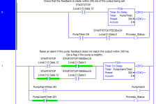
If you want Process_Status to be set when the pump is confirmed as running, use something like Rung 0.

It is often desirable to raise an alarm if the feedback does not follow the output. In this case you might use something like Rung 1.

(Don't use both rungs together: they are independent examples, which both set Process_Status using different methods.)

Also note that this only checks the state of the output. It does not include logic for actually starting the pump - you would have to use the output instruction and whatever conditions are required to run it. I'm not sure why having it the "same rung" is important to you; it's possible to keep adding branches, as I have done, but it's often neater to use separate rungs.

Regards,
Ian Shaw

Rung2.PNG
 
Last edited:
Hello Damian,
Yes, I have used a timer as you can see to my reply to Ken, but it is not so easy for me to use a TON on the same rung. I have to Start the motor (1=Start, 0=Stop), wait a fix time of 300-500 ms and then to check if the input motor feedback which should switch to 1 with start and go back to 0 with stop following the start/stop output signal.

It seems to count, but as the timer counter counts to jump and I can not see if the Accumulator reaches the set limit preloaded, I do not know if it works properly or not. Ken says that definitely happens as the timer is reset continuously before it reaches the limit.
 
It helps to clearly define the task you want to achieve.
Is this correct ?:
Using only a single timer, detect the alarm condition that the contactor feedback does not go on when the contactor coil is activated, and detect the alarm condition that the contactor feedback stays on when the contactor coil is deactivated.

You dont have to put multiple output instructions in series as Ken does. It is merely a compact way to write the output instructions.

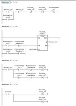
Here is an interpretation in STEP7 that can work exactly the same in RSLogix:

timersample.jpg
 
Hello Damian,
Yes, I have used a timer as you can see to my reply to Ken, but it is not so easy for me to use a TON on the same rung. I have to Start the motor (1=Start, 0=Stop), wait a fix time of 300-500 ms and then to check if the input motor feedback which should switch to 1 with start and go back to 0 with stop following the start/stop output signal.

It seems to count, but as the timer counter counts to jump and I can not see if the Accumulator reaches the set limit preloaded, I do not know if it works properly or not. Ken says that definitely happens as the timer is reset continuously before it reaches the limit.

What you have done is created an oscillator. The timer is going to just continuously reset itself with no regard to logic.

The OTE instruction you begin your network with, "start/stop" is not a conditional statement. Look back at another thread you created where Daba spent some time explaining the difference between INPUT type instructions and OUTPUT type instructions.

http://www.plctalk.net/qanda/showpost.php?p=489885&postcount=40

You REALLY need to understand these things before doing anything further. RSLogix5000 gives you a lot of rope with which to hang yourself, and that is exactly what you're doing.

The first real question is, WHY are you trying to do this all on one network? It is considered good practice to keep your networks small and focused.

The second question is, why not just follow Ken's, Ian's, or Jesper's examples?
 
Thanks Ian, the second solution is exactly what I was looking for. What can be done instead in the case that if an input is off (zero), then I have to perform a certain subroutine (JSR) every 10 seconds?
 
Damian OK, now with the examples of Ian and Ken I understand how the contacts language works. It is not easy to get into the ladder logic to a programmer who usually prefer to use assembler and C. Really must think of the input tests on the left and the generation of outputs on the right and read it as a current flow from left to right. This is more easy using only contact, bus using timers it is a little more complex.
 
Running a subroutine periodically

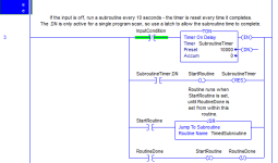
Try something like this.

This logic completes the subroutine even if the input condition goes on when the routine is still running. That is, once it has started, it runs to completion. This may not be what you want.

You should also consider what should happen if the subroutine takes longer than 10 seconds to complete, if that is possible on your application.

-- Ian

TimedSubroutine.PNG
 
Sorry Ian, I should integrate your second rung with alarm control in a function that:

0 - Open two valves,
1 - Wait 500 ms
2 - Set StartPamp relay = 1 to start the pump motor,
3 - Wait 300 ms
4 - Check pump motor input feedback (it rises to 1 if Start OK),
5 - If input feedback = 0 set alarm else motor pump OK

How is it possible to retry from point 2 to 4 3 times before to set alarm ?

Thanks for your teachings Ian, I hope not to ask too much for your help!
 
What will the retries achieve for you?

In most applications, I would strongly advise against the "3-try approach". It looks like your pump output is supposed to stay on to run the pump. If it doesn't work first time, it is extremely unlikely to work just because you switch the output on and off a few times, as if the PLC is a frustrated operator with a pushbutton.

If the pump fails to start first time, raise the alarm and take appropriate action.

If you just need more time for the pump to start, extend the timer to longer than 300 ms.

If you REALLY need to re-try, you need a counter (or even just a register) to count the attempts, then a timer or space out the tries. I might do this for sending communications messages to another controller, but I would avoid it when controlling equipment, unless I had a good reaso.

-- Ian
 

Similar Topics

Build error occurs with TON ladder logic command. Time Input expected on block. Using Integer Tag under Control Local, and then hard number 19...
Replies
2
Views
750
I have an SLC 503 running a machine with a scanner and 1794 RIO. One of the functions is a register motor on a printing cylinder. The manual 3...
Replies
3
Views
1,273
Hello all, I am using a temposonic R series linear transducer for positioning of a lower ram on a hydraulic powdered metal press. The transducer...
Replies
7
Views
1,935
My first post so I am going to try my best.:D I am totally new to RSlogix 5000, all my previous work was on 500. I am working with a...
Replies
14
Views
5,561
In the code below I have what should be, in its current condition, a simple cycling up counter with a delay before recycling. But as it is shown...
Replies
36
Views
8,155
Back
Top Bottom