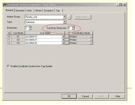
Transform Dimension

dr_cronik

Member
Join Date
May 2012
Location
United Kingdom
Posts
47
Hi All

I am setting up a Coordinate System in RS5K. It is a cartesian Type with axis X,Y,Z.

I am a little confused as to what the Transfrom Dimention setting is. Can anyone shed a bit of light on this???

Thanks
 
Dr Cronik,

It is Independence Day (from guess what?) here, and most of the old boys who could help you with that are out celebrating!
 
Hope you all had a good Independence day and the party hangovers havent left your minds to cloudy to share some of your much treasured knowledge.
 
Yes we did - lots of fireworks simulating the cannon fire in the War for Independance battles. I did hear of one triggering malfunction, a 30 minute fireworks show that sent off the whole works in 45 seconds. They said it was one big ball of fire!
 
Hi All

I am setting up a Coordinate System in RS5K. It is a cartesian Type with axis X,Y,Z.

I am a little confused as to what the Transfrom Dimention setting is. Can anyone shed a bit of light on this???

Thanks

The dimension setting of a coordinate system could be 1, 2 or 3, depending of number of coordinate axii to be used within the motion application.
A 1 dimension application is strictly linear.(X)
A 2 dimension application will perform within a plane. (X,Y)
A 3 dimension application will operate within a space. (X, Y, Z)
 
Yes I got this part what, I am unsure of is the selector box to the left of the dimension selection box

This box is called Transform Dimension?

transformDim.JPG
 
I do not have the 5000 software, but from my old student days studying Matrix Arithmetic, a 3-dimensional array (say 3 x 3 x 3) can be mathematically transformed to a different array. Usually this is done by multiplying by some other array of numbers. Back then we limited the array size to about 3x3x3 because all math had to be done manually!
 
Last edited:
I see.
The "Transform" function refers to the different (than the Units tab specified)dimensional units to be used for the number of axis to be "transformed".
Theoretically you could use up to three different units for a three dimensional system.
With a Transform Direction set to "0", when within the Geometry tab, there are no optional fields when defining a length or offset.
If set to "1", you will have two choices.
For SCARA robotics applications the "2" Transform Direction setting is to be used.
 
ok that makes some sense I see the link length inputs in the Geometry Tab however this is always disabled for a cartesian robot, does this not apply to a cartesian.
 

Similar Topics

Hello I'm looking for a simple way to transform numericInput Fields into numeric Output. I made several supervision screens with hudreds of...
Replies
7
Views
764
We are doing a proof of concept to try the following 1) get data from KepServer 2) The Data will be transformed eg: a Status code of 1 gets...
Replies
0
Views
1,214
Hi All, I want to know the dimensions of Allen Bradley PLC (1769 L19ER-BB1B) compact logix. Please let me know if anyone knows. Thanks in Advance.
Replies
3
Views
1,379
Hello all, New to this forum and I am teaching myself PLCs and learning more about panel building. I have a question that concerns fuse types. I...
Replies
7
Views
2,993
Hi Just got one of these to upgrade my home pc (P4) Spent a few hours putting my software on (Logix5,500,5000, MicroWin, S7 stuff, GX Developer...
Replies
10
Views
3,153
Back
Top Bottom