DIY Repairing a PLC?

gedds1993

Member
Join Date
Jul 2012
Location
South East USA
Posts
27
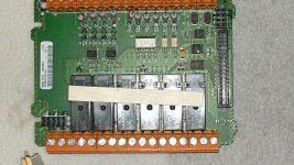
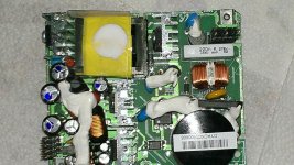
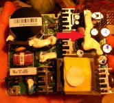
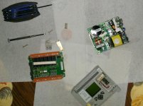
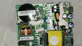
I have been working for my employer for almost two years now. Getting into PLC's right after high school makes me still relatively new to this field. On a side note I will be attending college this fall semester and majoring in electrical engineering with a minor in industrial electronics. I am sure I will be learning much more about this subject in school, but my main question is: Is there anyway to teach yourself how to repair a PLC that has been burnt out or is otherwise not in proper working condition? Also is there any self help on this subject. I understand that this is a completely different field then programming, but I figured it would be beneficial to learn to do. I am also sure it would help further my understanding of PLC's. I am not sure if this question is even possible but I would be very appreciative if anyone can help me. Right now I have an Allen Bradley 1100 torn apart. I know the problem is +-24v power supply on the inputs. Although I do not know what any of the parts are underneath and I am not 100% clear on how to test them. Again I understand that this is probably a task to large for this form and I should just wait till I get my schooling but I would very much enjoy and benefit from being ahead of the game. Pictures of the disassembled 1100 are below.
IMAG0026.jpg IMAG0028.jpg IMAG0029.jpg IMAG0030.jpg
 
Generally speaking unless you are going to work for a repair house or live in a third world country, it is not economically viable to do repairs to these things. Especially the really low end device you have.

Regardless, can you start by explaining how you came to this conclusion.

"I know the problem is +-24v power supply on the inputs."

What are the symptoms that led you to this conclusion. Understanding that will help narrow the focus so to speak.
 
People just don't do component level repair anymore. Have you known anyone who tried to repair a computer motherboard lately?

However, due to the higher cost of PLC, there are still specialized firms that do PLC component repairs. Not something people here do, it's just isn't worth out time.

Not sure about rest of the folks here but in general, you learn how to test each part, resistor, capacitor, etc for proper function then replace the bad one from the circuit board.
 
Generally speaking unless you are going to work for a repair house or live in a third world country, it is not economically viable to do repairs to these things. Especially the really low end device you have.

Regardless, can you start by explaining how you came to this conclusion.

"I know the problem is +-24v power supply on the inputs."

What are the symptoms that led you to this conclusion. Understanding that will help narrow the focus so to speak.

Well I figured it would be worth it to learn somethings on this because of the fact that it is not expensive and that if I hurt it I wont be hurting my wallet either.

My conclusion to the power supply on the inputs is because when the unit is fully powered up the inputs are not recognized and when i put a meter to the + &- terminals on the 24v there is no voltage.
 
People just don't do component level repair anymore. Have you known anyone who tried to repair a computer motherboard lately?

However, due to the higher cost of PLC, there are still specialized firms that do PLC component repairs. Not something people here do, it's just isn't worth out time.

Not sure about rest of the folks here but in general, you learn how to test each part, resistor, capacitor, etc for proper function then replace the bad one from the circuit board.

Well where I work I could make a more on top of what I am making if I can learn to repair PLC's in general. Its not really about the money but more to the experience learning to repair them would give me.
 
Welcome to the forum!
I agree with what the others have said. Most but not all PLC's are either disposable or need factory repair. There is little information such as schematic diagrams or parts identification available at the component level. It is just not cost effective if you consider technician time and production downtime. You would need to have the proper testing equiptment and adequate volume of work similar to a full time repair facility. Having said that, if you have skills to troubleshoot for defective or burnt capacitors, resistors and circuit traces, then don't be afraid to at least make this type of primary level repairs.
 
Last edited:
Welcome to the forum!
Most but not all PLC's are either disposable or need factory repair. There is little information such as schematic diagrams or parts identification available at the component level. It is just not cost effective if you consider technician time and production downtime. You would need to have the proper testing equiptment and adequate volume of work to warrant a full time repair facility. Having said that, if you have skills to troubleshoot for defective or burnt capacitors, resistors and circuit traces, then don't be afraid to at least make this type of primary level repairs.

Thank you for the warm welcoming! :ROFLMAO: Correct me if i am wrong but arnt the things you listed mostly what a circuit board is made up of and from what i am told mostly those are the things that go bad on them...i could be very wrong but then again thats what this form is for, to learn what you dont
 
The inputs on a ML1100 are not powered internally you need to power them externally.

Not all ML1100 have that DC sensor supply, which one do you have?
 
My conclusion to the power supply on the inputs is because when the unit is fully powered up the inputs are not recognized and when i put a meter to the + &- terminals on the 24v there is no voltage.

Ok, that is a good start. Are you sure you are supposed to get 24VDC out of those terminals as opposed to having to supply 24VDC to them? Usually your inputs are isolated such that you can interface them with an isolated power supply. Then on the inside they are opto-couplers that transmit the signal to the rest of the circuitry. So we need to make sure the real problem was just that it was hooked up wrong. Can you provide the exact Part# and the pins you are referencing?


EDIT: Mickey you sly dog. Always 1 minute ahead. That's what I get for being long winded!

The CAT.# : 1763-L16BWA SER:B REV:D FRN:11

Well i build trainers everyday and I have wired up probably 100 of these before. Im not going to say i could have wired it up wrong but i triple checked it to make sure the PLC was bad. My boss even checked it. Honestly i am just going off of what he told me should be wrong. Then again there is a good chance i didnt understand him well. As far as I know he checked the +&- 24vdc with the meter and the inputs. There was no voltage and the inputs were not recognized.
 
The first two places I would check are to make sure there are no cracked solder joints where the 24VDC out comes from the PCB. Then, I would look for the 24VDC voltage regulator that should be one of the two black similar looking heat sink mounted three prong devices. One is probably for 5vdc and the other is probably for 24vdc.


Edit:
Actually I count 4 that look like they could be a voltage regulator.
 
Last edited:
So the terminals labled DC out are not giving voltage?

The first two places I would check are to make sure there are no cracked solder joints where the 24VDC out comes from the PCB. Then, I would look for the 24VDC voltage regulator that should be one of the two black similar looking heat sink mounted three prong devices. One is probably for 5vdc and the other is probably for 24vdc.


Edit:
Actually I count 4 that look like they could be a voltage regulator.

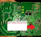
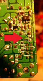
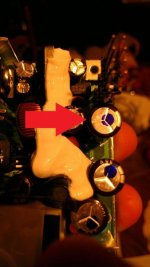
No, No voltage. Upon inspection of the +24vdc input terminal, i trace the circuitry to the pin out and from there to the back of the PCB on the solder point. I found what looks and smells to be a burn mark (kinda hurts getting your nose that close...it pokes ya and stuff :D) shown in image 31 and a closer view in image 32. In image 33 this is the cluster i believe that is with in rage of that scorch mark. and in image 34 i believe that is the resistor or what ever it is that go fried so to speak

IMAG0031.jpg IMAG0033.jpg IMAG0034.jpg IMAG0035.jpg
 

Similar Topics

Im trying to make my own DIY ControlLogix power supply and have had some success, but not every module powers up. I am using 4 seperate power...
Replies
7
Views
920
So I decided to build a very simple PLC to put all my knowledge into one fun project. The question I'd like to throw out there relates to the real...
Replies
3
Views
1,824
Hi! My friend is an electrical technitian who wants to know if it's possible to build a DIY memory cartridge with an EEPROM for use in S7-200 PLCs...
Replies
0
Views
1,143
Hi everyone, I'm looking at a project that will require operator intervention to "simulate" valve/motor feedbacks and analog values. In googling...
Replies
2
Views
1,940
Hi, I've noticed that CO2 controllers are retarded and sell for 500 $ Can you tell me how I could assemble a CO2 sensing chip, then read the...
Replies
16
Views
3,977
Back
Top Bottom