Newbee questions writing Mitsubishi ladder code ?

Christian_IA

Member
Join Date
Jul 2012
Location
Randers
Posts
9
Hi all.
Sorry for the mayby extreme newbee questions writing Mitsubishi ladder code but there are something I can't figure out :)
I have a demo version of GX Developer and would like to try to write some of the example programs from the manual for one of the special function blocks that I have in stock (FX2N-4AD-PT) but I can't get the ladder to look as in the example.
I will try to add pictures here to show:
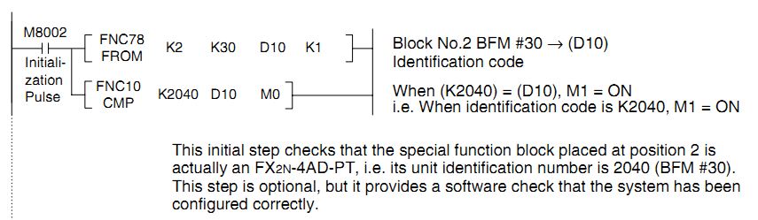
Below are the part from the manual:

ladder_part_fx2n-4ad-pt_manual.jpg


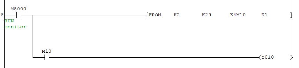
I have problems getting the part FROM right, I can't write FNC78 together with the FROM as you can see here:

wEW7f9RLlrrfgAAAABJRU5ErkJggg==
ladder_part_fx2n-4ad-pt_gx_developer.jpg


Do anyone knows if it's needed ?

/Christian
 
I dont believe you need to worry about that. Its been some years since my last mitsi program and never had an instruction written in that format.
 
Last edited:
Hi :)
Thank you very much.
Even that I'm a quite experienced embedded software developer my PLC programming skills are just above zero so my learning curve are pretty much like some of the maountain climbs in le Tour de France so I have tons of questions.

Can I ask you some of them here in this thread ?

/Christian
 
I'll confess immediately my mitsi knowledge is old and very elementary compared to guys like goody as its been some years since my last full mitsi program. However please feel free to post away i am a novice just like you.
 
Thanks, I will ask some questions and lets see where it get me :)
In the ladder diagrams, I have understood that the left side are the inputs and the right side the outputs.
Looking at this:
ladder_part_fx2n-4ad-init.jpg


In the left side the exmaple programs I have for this A/D block which in the example are position block number 2, the first is named M8002:
- are the M short for Memory ?
- Why is it 8002 ?
- does the xxx2 mean block 2, counting from the PLC=0 ?
- why 8xxx ?
- In the FROM statement:
-- Are the K2 for the 2. block ?
-- Are the K30 for the buffer memory BFM #30 ?
-- Are D10 then some variable that will then contain what is fetched from block 2 BFM #30 ?
-- What are the K1 part then ? could be that it is the number of words read ?

- In the CMP statement (to me it looks like they have made an mistake mixing M0 and M0, am I correct ?):
-- The PLC compares the content in D10 with constant 2040 and if true setting M0/M1 on ?

Are all this too much for you please say so :)

/Christian

M bits are the internal relays of the PLC. You are free to use most of them in your program. There are a number of bits that are special relay bits to perform specific predefined tasks. M8002 is a initial pulse bit. This will be true once at power up, (or going from stop to run), and will not happen again until the power is again cycled. Go to Mitsubishi's website and download the FX programming manual. In there is a list of all the special relays and their functions. I use GX Works 2 but I believe if you go to the help menu in GX Dev. there is a list of the special relays and their functions there also.
K in front of something just signifies that it is a constant. In your example K2 is just telling the PLC that the module you are configuring is the 2nd unit attached to the right side of the PLC. K30 is the buffer memory location and D10 is the data register it is going to put the data in. And yes, the K1 is the number of words read.

In the compare M0 turns on in the event that the constant value of 2040 is greater than the contents of D10. M1 will turn on in the event that 2040 equals the data in D10. M2 will turn on if 2040 is less than the data in D10. This is detailed in the programming manual as well.

Hope this helps,

Dave
 

Similar Topics

Our customer has a site with 3 SLC 5/03 PLC's, one main PLC that gathers 7 AI from the two others via radio (no cable possible since on a rotating...
Replies
2
Views
4,130
So, just to start, I am not an engineer, but a sort-of self taught programmer. And I am familiar with RSLogix-500, but I am just learning...
Replies
23
Views
6,797
I'm trying to debug the code for a automated crane, that we let some programming students revamp for us. We went from a slick 500 to compact...
Replies
2
Views
1,342
Good Morning All, I am a chemical engineer that has recently been tasked with creating live trends for a plant that I have just been moved to...
Replies
3
Views
1,921
Greetings, (My first post) I have a MicroLogix 1100 Processor. I have downloaded RSLinx Classic. I have also downloaded RSLogix micro English...
Replies
24
Views
8,926
Back
Top Bottom