Medicine Dispenser

jacobblue

Member
Join Date
Jul 2012
Location
Sydney
Posts
4
Medicine Dispenser
We are doing a plc-based project, medicine dispenser, we are told to dispense medicine at user's desired time intervel and number of times per day. When it is time to dispense, a buzzer will sound to alert the user. The buzzer sound will be deactivated when the user opens the dispenser drawer(with motion sensor attached), take the medicine and closes it. After 8 rounds of dispensing medicine, it will alert the user to refill the medicine dispensing compartment.We are using Matsushi ta FP0-C14CRS Terminal Block Type PLC with two expansions sets of FP0-E16RS for the inputs and outputs.
Help we need:
  1. For the customized time intervel, we would like to have a 1-9 up and down counter and for the customised number of times per day a 1-5 up and down counter. We need help to design a circuit diagram and also like to know how to connect the 7-segment display to the PLC.
  2. We also want the medicine dispenser to be idle from the last intake of the day to the following morning (approximation of 7hrs).
  3. We would like to have a circuit of how to link the buzzer and motion sensor.
 
We need help to design a circuit diagram ...
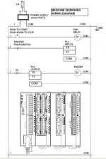
Even though you don't deserve it, from human kindness and pity on poor students, I will help you with this first part. Note that this diagram came only from my feeble thoughts on what you said, and probably does have errors! It also has hidden code that identifies the source. Now it is your turn to post some of YOUR work.


Medicine Dispenser Wiring.jpg
 
Last edited:
Even though you don't deserve it, from human kindness and pity on poor students, I will help you with this first part. Note that this diagram came only from my feeble thoughts on what you said, and probably does have errors! It also has hidden code that identifies the source. Now it is your turn to post some of YOUR work.
You big softie!
 
I am feeling guilty. JacobBlue, do not wire your PLC output like my drawing - it could burn up you PLC output, or blow the fuse. Instead, look at the wiring in the Matsushi FBO User Manual.
 
Sorry for posting too much question.We have actually done the ladder logic and we now need help in doing the circuit diagram of the 1-9 up/down counter 7 segment and the connection to the plc .cause we are quite unsure of the connection .
 
We now need help in doing the circuit diagram of the 1-9 up/down counter 7 segment and the connection to the plc.
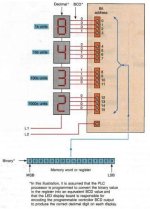
Here is a typical 7-segment LED connection to a PLC. Note that this one requires 4 LED inputs from the PLC outputs for each of the 4 digits. The 16-bit BCD number "0000 0101 0010 1100" is decoded to the correct decimal number displayed as "2,348". Decoding of the 4 sets of bits can be done by the PLC program, or by a special PLC output module.

Do you have a BCD output module, or must you set up PLC logic to do the decoding?

7-Segment LED- R1.JPG
 
Last edited:
They have a 7 segment (actually 8 the small dot.
the display will draw 10 mA per segment so you need 8 outputs and some resistors to limit the current as the PLC is 24 Volts
so 24 DIV 0.01 is 2400 ohm.
same for the buzzer as it will be a 5V one.
the switch with a resistor to ground of 2400 ohm
 
We have actually done the ladder logic and we now need help in doing the circuit diagram of the 1-9 up/down counter 7 segment and the connection to the plc.
Did you mean that the Up-Down Counter has a built-in 7-segment 1-digit LED display? If so, that is a different problem! We would need to know the brand and model number of the counter in order to help you, Jacob Blue.
 
Do you have a BCD output module, or must you set up PLC logic to do the decoding?[/QUOTE]

I think that we must set up PLC logic to do the decoding
 
I have done a previous program to decode 7-segment LEDs. Let me see if I can find it.

EDIT: I could not find the 7-segment encoder logic, but here is the logic for a 15-to-4 encoder logic. The 7-segment is similar.
 
Last edited:
Thank youuu! but I have slight problems understanding the connection. Can you please explain it briefly in words? Thanksss
 
Any encoder program takes a number and converts it to a number of individual digits that represent the Binary-Coded Decimal (BCD) place-holder value of each digit of the original number. If you have a 4-position 7-segment LED display "9999", then the left-most digit will be 1000's, the second 100's, the next 10's, and the right-most 1's. Your encoder loigic should translate the digits accordingly.

The easiest way is to make a table of all values, then look at which binary values need to be "1" for each value.
 
Last edited:

Similar Topics

Friends, I have a project that may be coming up shortly. The project is based on a dispensing line, the attached pdf. file has a...
Replies
7
Views
2,749
All, Has anybody seen/used an off-the-shelf automated tape or label dispenser? I'm looking at an application to dispense felt pads for...
Replies
3
Views
2,279
Back
Top Bottom