PLC and Terminal block and Sensor wiring selection

SergioB

Member
Join Date
Dec 2011
Location
Chicago
Posts
119
Hi y'all!

I have a general question regarding wire selection in panels and also wiring sensors to PLCs.

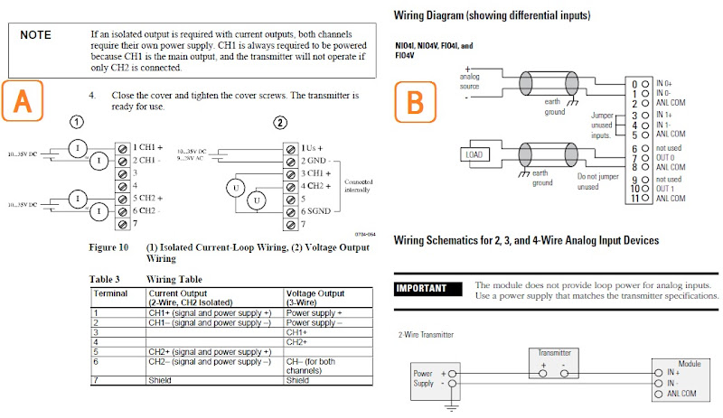
I've seen plenty of I/O cards in PLCs wired with pretty thick wires, as shown in examples A and B in pic below. However, AB sells the IFM-ready cables with very thin wires, shown in examples C and D.

plc_card_wire_selection.jpg


I've read that electrical engineers like the thicker cables because they are easier to manage and look a lot nicer than the thin ones. This seem to make sense, since the current is pretty low in these cards and does not require the thicker cables, is this a correct assumption?

Now, regarding cable selection to wire sensors to PLCs. The AB manual recommends using the "Belden cable #8761" for 2-wire sensor to analog I/O cards. Now, since I have a humidity/temperature vaisala sensor, it seems logical to me to be able to select another similar cable, but with 4 signal wires, is this a correct assumption?

So I'd like to stock a few rolls of wire that I can use for wiring my panels and sensors. Could you recommend the most common type of wire (and colors) for wiring 24v I/O discrete and analog cards to terminal blocks as well as wire for sensors? I'm looking for a way to stock a minimum amount of wire that can be use for multiple types of sensors and transmitters and for internal wiring between PLCs and terminal blocks and in some cases, 24vdc relays.

Thanks a lot in advance!
 
For 24 VDC discrete wiring you need normally 16 awg MTW if inside the panel and THHHN or similar outside the panel or something close to THHN all the way.

The this wiring for IFM modules is for in panel use only. The thin wiring for discrete does not hold up as well in the field and IIRC 18 awg is as ow as you can go for discrete anyway by code outside the panel.

Land you discrete wiring on the IFM module and then use the premade thin cabling from the IFM module to your I/O module

I always use 16 awg for field discree devices if it is a excess distance it is prolly time for remote IO at that point anyway.
 
Thanks for the reply. For the purpose of stocking a few rolls of wire, what wire would you recommend for wiring 2,3,4,5...-wire sensors as well. If you can recommend specific brands and suppliers, it would be very helpful.
 
The 'fat' wires in pic A would be a nuissance to my opinion.
The wires in pic B seems OK. I guess they are 1 mm2.
The wires in pic C and D comes from a cable so it is apsecial case, see below.

It is the voltage AND current rating that decide what kind of wire you can use. Normally, the wires must have the voltage rating of the highest voltage used in the panel section. For sensor and the like, there is nothing wong with for example 0.25 mm2 if only the voltage rating is OK.

The individual wires of the cable in pic C and D probably have a low voltage rating, but it is the cables rating that counts since the cable insulation is opened just at the terminal block on the card.
 
The 'fat' wires in pic A would be a nuissance to my opinion.

Yeah, I know. Surprisingly, I see these type of wiring a lot, so I was just hoping for someone to 'confess' that the only reason they used such thick wire in low voltage/current applications is because it would tend to layout straighter and neater than thinner wire.

The individual wires of the cable in pic C and D probably have a low voltage rating, but it is the cables rating that counts since the cable insulation is opened just at the terminal block on the card.

I plan on sticking with 24v, 0-22mA sensors and transmitters for my system.
 
Hi again. I hope there's someone out there that can answer my question regarding using single multi-lead cable instead of two separate 2-lead cables to connect my vaisala humidity/sensor transmitter.

I used a shielded belden 1307, 6-lead cable to connect my vaisala transmitter. I cut off 2 of the leads that I didn't need and used 2 leads to connect the humidity output (CH1:4...20mA RH:0...100%) and the other 2 leads to connect the temperature output (CH2:4...20mA T:-20...80°C). Wrapped drain wire to foil shield and attached it to plc chassis, as indicated in wiring instructions.

The problem I have is that the signals from the trasmitter seem to be incorrect, or rather, only one signal, the temperature one, seems to be correct. Moreover, the temperature signal seems to be coming to channel 1, rather than channel 2.

Is it possible that the 2 signals are getting interference from each other because I'm not using separate cables for each output? I'm using a AB 1746-NIO4I card and I seem to have read that these cards are very susceptible to noise and interference.

Looking forward to your comments.
 
It would be very difficult to believe that the signals are interfering with each other unless something simply isn't wired correctly.

The spec sheet I see shows Belden 1307 as 2 conductor, not 6.

In general, when doing what you are doing you would want each pair in the cable to be a twisted pair. Even better for each twisted pair to be individually shielded. Also check and make sure your jumper settings are correct, your using the correct terminals, and the config is correct in the software. I also wonder how you powered the transmitter, as I would expect that you probably had to bring 24vdc to it or similar and I would have thought you would have used the 3rd pair of wires for that.


You will have to elaborate on what makes you believe the signals are incorrect. You should check to see what the impedence is of the NIO4I module and see if that is compatible with the max impedence the transmitter can handle.

Regarding wire sizes, the heavy gauge use is partially related to conventional momentum. If you look at an IO card from the early 80's it is evident why large wires were used. Since most companies developed their standards for PLC wiring during this era, it is as usual difficult to get them to review their standards to see if they are outdated. Often the people enforcing the standards don't understand (or worse yet don't care) why they are what they are. As equipment has gotten smaller and more compact the need for revisiting wiring needs to as well. Many IO cards these days can't physically accomodate 16awg wire. I had an argument with a project engineer once almost a decade ago because he mandated a minimum 14awg on ALL I/O even though the I/O modules he also mandated could not even accomodate them. I had to physcially put them right in front of him with some wire and have him try to show me how I was going to stuff 14awg wire in a hole smaller than the wire was round.

I try to stick with 18awg with my low voltage 24Vdc if it is single core. If it is multi-core I am comfortable with 20awg as well. I rarely these days use traditional rack based IO anyhow. Even on the main panel I will mount a remote IO adatpter like an AENT and use slice IO. Then bring all the field wiring directly where it needs to go. It eliminates panel space, extra labor, extra points of failure, and the IO module are so inexpensive they are practically as disposable as a fuse.

Also, you will notice that for example 16awg MTW is much thicker than 16awg THHN. The jacket is really rubbery. Electricians like to use it on panels because it is more pliable and easier to tease and bend. Bottom line is common sense must rule.

Another thing with smaller gauge wires is how you are stripping them and how you are connecting them. Careless stripping on lighter gauges can easily hack off half your strands. Those smaller strands are also at greater risk of getting crushed or sheared off by a pressure plate termination. If you use spring clip type terminations then this is less of a worry. We have standardized on using ferrule ends or fork/ring terminals on everything. It forces the electricians to take greater care to make certain all the strands are straight and the end result tends to be much more professional and maintenance friendly. Also, if ferrules are mandated it is also common that a wire size that would normally fit un-ferruled all of the sudden is too big for the terminal once ferruled. So again, overspecifying gauge can also cause issues. Like everything else made today, wire terminals just aren't as tough as they used to be either. If you use too large of a gauge, you may damage the terminal when tightening.

It's all part of the fun!
 
Hi DamianInRochester, awesome explanation, thank you so much!!!

I used some belden wire i had laying around and took the last number in a series of numbers and characters, so i might have gotten it wrong.

Below are the wiring diagrams (tried to make them as small as possible) from both the vaisala sensor (figure A) and the AB analog i/o card manual (figure B). The vaisala is configured for current output and so is the i/o card. I wired the transmitter as shown in bottom diagram of figure B.

wiring_vaisala_hmt100_to_1746-nio4i.jpg


I believe the wiring is correct, but I have the feeling that I will need to use separate insulated twisted pairs wires for each output, as you mentioned. The reason I say the values are coming in wrong is because temperature reading seemd to be correct at about 60F, but humidity was a negative value. I tested sending just one signal at a time to channel one of the i/o card, and this time i did not get any negative values, so this pretty much isolates the wire as being the culprit? The ladder cmd is SCP with input between 6240 and 31208 scaled to 0-100 for RH and -20C-80C for Temp.

By the way, if i need to setup any parameters for the i/o card, where would i do this? I have RSLogix 500.

Thanks again!
 
Last edited:
So I'd like to stock a few rolls of wire that I can use for wiring my panels and sensors. Could you recommend the most common type of wire (and colors) for wiring 24v I/O discrete and analog cards to terminal blocks as well as wire for sensors? I'm looking for a way to stock a minimum amount of wire that can be use for multiple types of sensors and transmitters and for internal wiring between PLCs and terminal blocks and in some cases, 24vdc relays.

Thanks a lot in advance!

I like 19 conductor cable from TPC, Belden, I think Alpha makes it too. With 16awg wire color coded for DC or AC or even the multiple color code. Then you can have the IFM cables without two drawbacks:
1) Price
2) infinitely variable cable length

We have a lot of the A/B IFM cables and they are very nice, however in all of our installations there are places where the cables is wig-wagged in the panduit and I don't like that. And, I have had one instance where the connector was broken and it was more time, money and work to replace than a single terminal block of my choosing would have been.

EDIT: Looks like Belden has switched up their lines...looking for a good link...
 
i tested sending just one signal at a time to channel one of the i/o card, and this time i did not get any negative values, so this pretty much isolates the wire as being the culprit?
for me this says you have checked 1 channel what about channel two?
 
Hi DamianInRochester, awesome explanation, thank you so much!!!

I used some belden wire i had laying around and took the last number in a series of numbers and characters, so i might have gotten it wrong.

Below are the wiring diagrams (tried to make them as small as possible) from both the vaisala sensor (figure A) and the AB analog i/o card manual (figure B). The vaisala is configured for current output and so is the i/o card. I wired the transmitter as shown in bottom diagram of figure B.

wiring_vaisala_hmt100_to_1746-nio4i.jpg


I believe the wiring is correct, but I have the feeling that I will need to use separate insulated twisted pairs wires for each output, as you mentioned. The reason I say the values are coming in wrong is because temperature reading seemd to be correct at about 60F, but humidity was a negative value. I tested sending just one signal at a time to channel one of the i/o card, and this time i did not get any negative values, so this pretty much isolates the wire as being the culprit? The ladder cmd is SCP with input between 6240 and 31208 scaled to 0-100 for RH and -20C-80C for Temp.

By the way, if i need to setup any parameters for the i/o card, where would i do this? I have RSLogix 500.

Thanks again!

Can you provide the exact part/model number of the Vaisala unit? It still don't think your isses are related to the cable.

What is the distance between the transmitter and the PLC?
Did you take care to read the note about the AB analog inputs NOT providing loop power?
 
The ladder cmd is SCP with input between 6240 and 31208 scaled to 0-100 for RH and -20C-80C for Temp.

Also, the input resolution I believe is actually 3277 to 16384 for 4-20mA inputs. I believe you must have used the analog output resolution by mistake.
 
I like 19 conductor cable from TPC, Belden, I think Alpha makes it too. With 16awg wire color coded for DC or AC or even the multiple color code.

Sounds like an excellent idea, I'll start looking for some opportunities on eBay. Thanks!

for me this says you have checked 1 channel what about channel two?

Good point, I'll look into that as well. Thanks!

Can you provide the exact part/model number of the Vaisala unit? It still don't think your isses are related to the cable.

What is the distance between the transmitter and the PLC?
Did you take care to read the note about the AB analog inputs NOT providing loop power?

Sorry, it's a vaisala hmt-100. I'm only testing, so it's around 6ft total distance. 3ft from transmitter to terminal block and another 3ft from terminal block to plc module. Yes, I'm providing power with external 24vdc power supply. I'll switch to connecting shield and drain at the transmitter end (currently connected at the plc end, at chassis tab) and see what happens. Thanks a lot!

Also, the input resolution I believe is actually 3277 to 16384 for 4-20mA inputs. I believe you must have used the analog output resolution by mistake.

I'll rewire the transmitter and test with those parameters. Thanks a lot!
 
Surprisingly, I see these type of wiring a lot, so I was just hoping for someone to 'confess' that the only reason they used such thick wire in low voltage/current applications is because it would tend to layout straighter and neater than thinner wire.
No, I won't confess. I have used what you call "thick wires", but I call them low-voltage shidelded signal cables. These are used where there is a need to exclude higher voltage from being induced onto the signal cables. A shielded wire has an outer mesh or foil shiled around the inner two signal wires. That is what makes it thicker.
 
A shielded wire has an outer mesh or foil shiled around the inner two signal wires. That is what makes it thicker.

Thanks Lancie1, but the ones I was talking about from the sample pic on first post, the blue wires in figure A, were not two inner signal wires, but a single thick wire.
 

Similar Topics

We're using a lot of Allen Bradley IFM modules (Connecting to ControlLogix I/O cards) in our panels, and are considering replacing them with...
Replies
1
Views
3,361
Dear all How to open .b0$,b1$,b2$,da1,ix$,lx$ allen bradley plc2 files. Please help Thanks & Regards Afeef
Replies
12
Views
4,351
Hello guys i wish if you could help me out with your experience. I must install a PLC on the diesel driven machine and PLC must measure the the...
Replies
3
Views
2,804
Hello, I would like to change the way we currently login to our PanelView Plus terminals. Currently we use the standard terminal features, Logon...
Replies
6
Views
3,311
hello friends i want to send some specific ascii character from PLC to my PC hyperterminal can any body help me in achieving this ?? i am very...
Replies
2
Views
1,907
Back
Top Bottom