microLogix 1000 and RsLogix 500

Dwaladust

Member
Join Date
Feb 2004
Posts
4
Hello I was directed to this site and told I might find an answer to my problem, here goes: I am writing a paint factory program on a microLogix 1000 using RSLogix software, the problem i am having is that when the input on the main program goes true it goes to a jump instruction. From there it gos to the subroutine and immeadiatly starts a timer to run the specified color. However the timer in the subroutine does not actually start timing the pumps start but the timer that runs them does nothing just sits there, if anyone can give me an idea of what i have to do to fix this problem. I used this same equipment to write a 4-way stop light program with subroutines and it worked just fine so after various configurations on my input and bits to run this program i am at a loss.
 
you said:

when the input on the main program goes true it goes to a jump instruction

you probably meant to say "... it goes to a JSR (Jump to Subroutine) instruction." ... this is picky but usually the problem is something trivial ... try to be more specific in the future ...

now then ... right-click on the timer's address (example: T4:0) and then select "Find All" from the pop-up menu ... use this search feature to make sure that you haven't programmed an RES (Reset) for that timer ... also make sure that you haven't programmed the same address (example: T4:0) for another timer anywhere else in the program ... check anything else that could be controlling your timer through the "backdoor" ...

also stay in the questionable subroutine file and right-click on a "real-world" output (example: O:something-or-other - NOT B3/something-or-other) and try to toggle the output on and off ... if you can toggle the bits this way, then your processor is probably NOT scanning the subroutine that you're looking at ... is there anything in the subroutine file like an RET (Return) or a TND (Temporary End)? ...

if this doesn't help, you might want to consider posting your program ...
 
Ron's got you on the right track.

Be careful about putting timers in subroutines. Generally, you shouldn't do it unless the routine is executed every scan. Strange things can happen, otherwise. This is because you can leave the timers partially timed-out, until the next time you execute the routine.

Also, be careful of setting bits in subroutines. Even if you use a coil output command, it can act like a latch in your program. If the bit is set high on the last scan through the subroutine, it will stay on until the next time you execute that rung.

AK
 
Yes it is a JSR sorry for being vague, I actually have 7 subroutines 6 of them are different paint colors and the last one is a rinse cycle all of them have a seperate timer in the subroutine and all are addressed differently. I do have a return (RET) and a reset for each individual timer in the subroutine. All other inputs in the subroutine are run off of the (EN) enable or (DN) done bits of the timer the type of timer i am using is a (RTO) retentive timer-on-delay hence the need for a reset inside the subroutine. i will try to post the program i need to change the formatting.
 
Ok just want to say thank you i have found and solved the problem, it was the timers inside the subroutine, i moved them out to the main program and it works fine now so thank you for you advice.
 
well, if you're happy, I'm happy ...

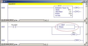
but I've got a hunch that if you'll remove that RET (Return) then Subroutine #7 MIGHT just start working the way you expected it to ...

[attachment]

since you're using an RTO timer, then you need the RES (Reset) to take it back to zero when you're through with it ... that part is correct ... the problem I believe you're having crops up when the timer gets done ... when rung 0005 executes with a TRUE done bit, the RET immediately kicks the processor right out of the subroutine and sends it screaming back to ladder #2 ... specifically, the processor never gets a chance to execute the RES and reset the timer ...

actually you don't need the RET (Returns) in your program at all ... the processor scan will automatically "return" when it gets to the end of the subroutine ...

think about this ... when you said:

the timer that runs them does nothing just sits there

I've got a hunch that what you meant to say was something like:

"The timer's accumulator runs up to its preset and the done bit comes on ... but the timer won't reset to get ready for the next cycle."

if that's what you saw, then I think the solution I offered above should take care of your "timer won't reset" problem ...

but then you're probably going to have another problem pop up ... your simple switch controlled rung for the JSR in ladder #2 is still going to be true ... so the "timer controlled" cycle will continually run over and over again ... you need some way to make the JSR rung be true for just one cycle of the timer ... notice I did NOT say "for one SCAN" ... work that one out and you should be ready to roll ...

extra res.jpg
 
Last edited:

Similar Topics

Hello all, I am trying to write a auto/manual mode programe for this machine control. I can get the outputs to turn on when i am in...
Replies
11
Views
2,444
RE: RSLogix 500 Starter for 10pt Micrologix 1000 Greetings To All: I am in possession of an Allen-Bradley 'Starter Pak Toolkit' CD-ROM. This...
Replies
6
Views
12,987
"Hello! Good day! Excuse me, I have a question regarding the 1761-NET-ENI. RSLinx has already detected it but it's not connecting to the PLC...
Replies
4
Views
92
Hi all, We have a very old pit pump system running on Micrologix 1000. Now, whenever there is an alarm for high conductivity, we want that alarm...
Replies
5
Views
1,247
Looking at a Micrologix 1000 1761-L32AWA, I tried to connect using the 1761-CBL-PM02 through a Serial to USB converter (This setup was used...
Replies
2
Views
978
Back
Top Bottom