practice design critique?

david90

Member
Join Date
Apr 2010
Location
ca
Posts
202
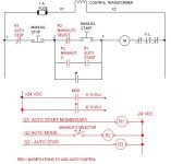
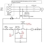
For practice, I designed a system using autocad electrical with the following specs, and I would like some critiques on my design. I'd like to know if there are any safety concerns with my design.

1. System shall contains an estop, auto/man selector switch, start and stop pushbutton.
2. When in auto mode, the 10hp motor shall be under the PLC's control when the start button is pressed.
2. When in manual mode, the 10hp motor can be manually start and stop with the start and stop pushbutton.


33a3rww.jpg

ilkm0z.jpg
 
Last edited:
I'm not sure why Start and Stop buttons are being feed to the PLC. In 2) you say that the motor is under control of the PLC when the start button is pressed, shouldn't it be under control of the PLC when selector is placed in auto? It's what I would assume.
 
It's OK to run an Estop contact into your PLC but it should be for indication only. You will need additional contacts and/or components to create hardwired safety outside the PLC.

I'm a little confused by your last two points. Is this suggesting that the PLC is to be bypassed when in manual mode? That wouldn't make much sense so I'm assuming it can all be done in software and no extra wiring is necessary.
 
I'm not sure why Start and Stop buttons are being feed to the PLC. In 2) you say that the motor is under control of the PLC when the start button is pressed, shouldn't it be under control of the PLC when selector is placed in auto? It's what I would assume.

I should been more clear. When in auto mode, the start button runs the program inside the PLC when pressed. When the PLC program runs, it runs/stop the motor in a certain sequence.

When in manual mode, the motor can be latched on by pressing the start button and stop by pressing the stop button.
 
It's OK to run an Estop contact into your PLC but it should be for indication only. You will need additional contacts and/or components to create hardwired safety outside the PLC.

I'm a little confused by your last two points. Is this suggesting that the PLC is to be bypassed when in manual mode? That wouldn't make much sense so I'm assuming it can all be done in software and no extra wiring is necessary.

Yes the e-stop to the PLC is for indication purpose. The estop is in series with M1 and it will kill the motor if pressed.

Yeah you're right about the implementing the manual mode with software.
 
Here is the revised schematic. In this schematic, the manual and auto mode are software implemented. This version is a lot simpler and I really like that.

Once again, are there any safety issues with the schematic?


wikd8h.jpg
110jimx.jpg
 
dont be afraid to use your motor run indicator from a PLC output

as far as the E/Stop
Ask - what is your machine doing?
this wiring is a Cat. 1 level safety system
so it is correct for that level.
 
I concur. Make it straight in and straight out. Bring the OL relay to a spare input, so the PLC "knows" when there's an OL condition....Oh, I see you did that with an interposing relay. Is that extra relay required? I like to have a 2nd N.C. contact to monitor with the PLC, but if there is only one N.C. contact available, it must go in the starter coil wiring and I will use a N.O. contact as PLC input like you have it, but I can't think of any advantage to the interposing relay (CR1) unless they're in different panels (the PLC and the interposing relay) with different hazard ratings.
 
Last edited:
Yeah you're right about the implementing the manual mode with software.
3. When in manual mode, the 10hp motor can be manually start and stop with the start and stop pushbutton.
Look at your PLC Outputs to determine WHAT actions your PLC can make. Right now you only have Output O/1 which turns on CR2. This will allow one mode of control, Auto as you have it wired.

Technically, for a true MANUAL mode, when in Manual mode and Start is pressed, the control voltage should go directly to the motor starter coil, not to the PLC. Notice that your Specification #3 does not even mention the PLC at all - the motor has to start and stop by using only the buttons. Manual means that everything is done by hand and cannot be bypassed by some other device. Manual should work as a last ditch-method to keep the motor running if the PLC is removed, or other Auto wiring fails.

In the attached picture, the PLC has 3 outputs to control the Auto Mode.

The main point is that your wiring as is shows a hybrid system - it either does not have a true manual mode, or if the PLC is to also control manual, then there is no PLC output for manaual. If you want a true manual mode, then the Start button will either need two sets of contacts, one for Man Start and one for Auto Start, or you will need two separate buttons (not mentioned in your specifications). The Stop button can perform the Stop function for both Auto and Manual modes, but only if your control voltage for the motor starter matches and is common with the PLC output voltage. As for your Start button, I would ASSUME two sets of Start-button contacts for the purposes of the exercise.

In any case, your drawing needs some changes to correctly match your 3 specifications.

Man-Auto Schematic.jpg
 
Last edited:
It is easy in drawings to confuse the physical wiring with the PLC internal logic. It appears that as a minimum, you would need 3 PLC inputs and 1 PLC output, with wiring modifications as shown in this picture. You could do without the PLC Stop input if you are short on inputs. If you have plenty, then as Okie said, you could add one for a PLC motor starter overload input.

good point about how manual mode is not suppose to rely on the PLC to turn on the motor. In fact my first version of the schematic has that hardware manual mode. I can still the motor even if I remove the PLC.

The system specs is poor so I'm going to re specs it.

1. The system shall have 3 push buttons: START, STOP and ESTOP. The system will also have an AUTO/MAN selector switch.
2. When the system is in auto mode, pressing the start pb starts a PLC program that controls the motor (How the plc program controls the motor is not important.) When in auto mode and the stop pb is pressed, the PLC program stops.
3. When in Manual mode, pressing the start button latches on the motor and pressing the stop button turns off the motor.
4. The PLC shall be aware of the system's mode (Auto/man) and the system's ESTOP and overload condition.
 
Last edited:
David, that is a very smart move and a very good rewrite of the specs. Now we all are playing from the same music, and it is clear how the manaul and auto modes are supposed to work. Yes, your first drawing will work in manual mode, but not in PLC Auto. You need to add the additional PLC input points to allow creation of the auto mode in the PLC program.

STOP controls: It is smart and safe policy to always design any button or switch control that is labeled "STOP so that it will actually always stop the equipment, no matter what mode, step, or stage the system is in. In your first drawings, your STOP pushbuttons only work under certain modes. If a button only stops equipment in Manual mode or Auto mode, then it is your moral duty to make sure those buttons are labeled "Manual Stop Only" or "Auto Stop Only". The best way is to make a STOP button really perform the stop function, always.

I don't understand why my first schematic will not work in PLC auto mode. When the selector switch is in auto position, PLC input I/2 will be on (correction:the contact @ I/2 should be NC instead of NO). When input I/2 is ON, the state of the start and stop pb can run or stop the PLC program. When the selector switch is in man mode, input I/2 turns OFF and the PLC ignores the state of the stop and start PB. Thus the stop and start PB can't start or stop the PLC program when in manual mode.
 
Last edited:
I don't understand why my first schematic will not work in PLC auto mode.
A review of your drawing is what you asked for, and below I am commenting on your drawing, not your logic, your intentions, or your PLC program.

Your drawing will not work in PLC Auto Mode because you have not shown any physical way to get the PLC Inputs for "PB2" and PB3" into your PLC. For example, look at the Auto-Manual Selector Switch SS1. In your FIRST schematic drawing in Post #1 at the top, you show SS1 with TWO contacts, one for manual, one for auto. You use the manual one in the physical wiring, and you use the auto contact in your lower scematic for the PLC wiring. That is as should be, except that the left side of the second SS1 contact must be wired either to the PB1 Emerg Stop button or directly to 120 volts. In the top scehmatic you show it wired to PB1, but in the bottom PLC schematic, you show the left side of PB1 wired to 120 volts. It cannot be both!

However, for PB2, you have already used the ONE contact in the manual START PB, so there is nothing left for the Auto PB2 that is wired directly to the 120 volt power in your PLC wiring. You cannot use the same PB2 contact in TWO places (that are wired differently). If PB2 has two separate contacts, then those must be shown as such and labeled as such.

The same goes for PB3: you used it as a STOP button, with one side (wire 21) going to SS1 and the other side (22) going to the Start button. Now look at your PLC wiring. Here you show the ONE PB3 contact wired to 120 volts and PLC Input I/1. That is physically impossible. Either PB2 and PB3 have TWO sets of electrically separate contacts (WHICH ARE NOT SHOWN IN YOUR DRAWING), or you must provide separate pushbuttons (which should have different device numbers).

Notice that in the last drawing that I posted (Post #11), I show a place to put the STOP pushbutton PB3 so that only ONE contact is required for both the Manual and PLC Auto Input. For the Start button, I think the best method will require two contacts, and both those contacts should show on your drawing and be lableled (usually someting like "PB2-A" and "PB2-B").
 
Last edited:

Similar Topics

Hello guys, I'm pretty much bored this weekend and since there is snow outside, I decided to start new thread about PID's control design...
Replies
0
Views
5,552
Compactlogix controller, program has 28 conveyors that use TON's to start the conveyors. The TT sounds a warning horn during start and the DN...
Replies
10
Views
485
Out of interest, I'd like some thoughts on what would be considered best practice with regards to a 2-position turntable control scheme (see...
Replies
17
Views
1,136
I'm looking for some starter kits but there aren't so many on the market, so I'm thinking about buying individual components for my needs. I just...
Replies
15
Views
2,451
I'm building a S7-300 rack to work on my Siemens Classic Step 7 programming skills. I've worked now and then with Siemens hardware, usually...
Replies
19
Views
6,506
Back
Top Bottom