E-Stop Circuits

Jieve

Member
Join Date
Feb 2012
Location
USA
Posts
274
Hello Guys,

I was wondering if someone could quickly explain, maybe including a sketch or two, how a typical emergency stop circuit is wired. As far as I know, it should be normally closed and remove power from the PLC output modules and all machine actuators. I believe I had also read that there should be redundancy in the pushbutton wiring, meaning that more than one contact on the same switch should be used in case one should break. I also know that a relay (or a couple, redundancy?) is generally involved, but am not exactly sure where in the process it is supposed to be wired. Is the relay wired in between the +24V power supply and +24V bus connected to the PLC output modules/actuators or something, so that it can disconnect this power completely? Or how should such a circuit be structured exactly? I have also seen specific relays designed for emergency stop circuits, are there any benefits to using these as opposed to a standard contactor or something, for example?

Thanks for any responses!
 
A "typical" E-Stop relay, in the plants I've seen around the world, is wired as dual-channel inputs with a chain of mushroom-head pushbuttons wired in series with each other (i.e. each contact is closed when released). The safety relay contacts switch power to the coils of two contactors, whose load contacts are connected in series with each other to redundantly break both phase supply to motors and 24V to pneumatic actuators etc. In this way, one channel of inputs or one of the safety contactors can fail without affecting the function of the circuit. The relay will only reset after an E-Stop if it detects both contactors opened correctly, both input circuits are healthy, and a pushbutton has been pressed by the operator.

Note that this basic description is not common in isolation, as most real safety circuits include other safety devices such as light curtains, access gates and lanyards. There are further complications when you start needing to divided areas of plant into E-Stop zones, or if you are protecting particularly dangerous equipment. More general advice might be to download Pilz's safety design guide from their website and start looking from there! I would especially advise familiarising yourself with techniques of risk assessment since you will use these as guidelines in designing your safety circuits.
 
Last edited:
Thank you guys for your responses.

Binaural, thanks for that description. I am looking at a control cabinet wiring diagram and control cabinet built for educational purposes by one of my ex-coworkers, and it seems like the E-Stop circuits are just about what you described ... there are 2 contactors for each E-Stop Relay, whose outputs seem to be wired in series. There is some type of logic circuit built into the E-Stop relay, but I haven't looked at the data sheets so I'm not exactly sure how it works specifically.

The E-Stop contactor outputs are wired in series and shut off power to the output module of the PLC connected to the actuators. It doesn't shut off power to any terminal blocks or other main distribution circuits. Is this common? I would have thought that if I had a motor contactor connected to the PLC, for example, that the power should be cut from the source of the motor when E-Stop is pressed and not just the PLC output to the contactor, but maybe this isn't necessary.

As an introduction to E-Stop circuits for our students, we are building a simple conveyor system and need a realistic E-Stop circuit setup, without using dedicated E-Stop Relays - we have a lot of contactors we can use though. Is there a way you or anyone could draw up a simple circuit showing the proper wiring, sort of as you've described above?

Thanks so much!!!
 
Binaural,

I just read over your response again and noticed that you essentially already answered the questions about the E-Stop relay and the 3-phase motor cutoff that I asked about again in my second post. I should have waited until I was a bit more awake before responding to it. šŸ™ƒ

I've been thinking about this a bit and drew up a schematic for 2 E-Stop Buttons, 2 Contactors, 2 E-Stop Acknowledge pushbuttons, and an E-Stop LED. Is this a reasonable way of creating an E-Stop circuit without using one of those Safety E-Stop Relays?

(See PDF)

Thanks guys!
 
Last edited:
Additionally, a proper E-Stop circuit requires a secondary action (other than resetting the E-Stop) to reset.
 
A quick look at the circuit and I see that you should connect normally closed aux contacts from K1 and K2 in series with Ack1 and Ack2. So that if K1 or K2 do not function properly you are prohibited from reseting the emergency stop circuit. (K1 and K2 must be positively-driven/force-guided relays).

As Oakley mentioned, you want to have your start circuit designed so that simply reset the the emergency stop circuit will not cause the motor to restart.
 
Thanks for the replies guys.

<< As Oakley mentioned, you want to have your start circuit designed so that simply reset the the emergency stop circuit will not cause the motor to restart.

Wouldnt this be done in the software? In other words if in auto, and Estop was pressed, go back to idle mode and wait until the start button is pressed again?

Also, what are positively driven force guided relays?

Thanks!
 
I've been thinking about this a bit and drew up a schematic for 2 E-Stop Buttons, 2 Contactors, 2 E-Stop Acknowledge pushbuttons, and an E-Stop LED. Is this a reasonable way of creating an E-Stop circuit without using one of those Safety E-Stop Relays?

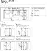
No. I would refer to the schematic of a safety relay.

pnoz.jpg
 
Last edited:
I thought I should point out that putting together an effective and legal Estop circuit requires more knowledge that will be transmitted via a single post.
I would go to the Pilz or Allen Bradley web sites and download their safety handbooks. Both companies put out a good one.
Be warned, they are a few hundred pages long, and I would think you would have to be familiar with the entire book to be able to design a good circuit, even when using correctly rated safety relays.
 
[W]hat are positively driven force guided relays?

Force-guided relays also called positively-driven relays, or positively-guided relays differ from general purpose relays in one key aspect. The auxiliary contacts will not close if a contact welds. This way the welded contact can be detected. This types of relay is specifically designed for use in safety-related control systems (see IEC 60947-1-1).

In your example, if K1 welds closed, how will you know? When you press e-stop K2 opens and everything appears to be fine but in fact you've lost redundancy. Some time later K2 welds, now when you press e-stop nothing happens!

With force-guided contacts (and a properly designed circuit) you can detect that K1 has failed and replace it before continuing. Because you have redundancy, K2 still performs the emergency stop function. So you maintain safety in the event of a single component failing and you detect that failure before it become dangerous.
 
If you're teaching people then teach them that a Risk Assesment should come first to determine the risks and associated control measures required. EN954 is no longer valid in europe and all new safety circuits (in europe) are required to conform to EN 13849 or SIL (ISO 61508); both of these standards require calculations of how reliable a safety circuit is.

Nick
 
Thanks for the responses.

Here is the situation - we have a simple conveyor system that came from industry (used to transfer PCBs for soldering) that is being used for educational purposes. Basically the system is safe, the possiblilty of anyone hurting themselves on this thing is practically non-existant. However, since it's for educational purposes, we're trying to make it realistic.

That being said, these students are not being trained to be electricians designing and building these circuits, nor am I giving them an entire course on E-Stop circuits. I just wanted something that might be an example of what one might find in industry. After talking to a few technicians from the US about it, they said that while this may not directly conform to today's european standards, there are tons of factories that are running E-Stop circuits that are setup exactly like this. (Not sure what european safety category this would be under).

Apparently I also did a poor job of conveying what "Acknowledge E-Stop" means, it is basically a separate pushbutton that restores control power to the system, not the same as pulling the E-Stop button out. So I'm posting the circuit again, now modified with Timbert's recommendation. In this case, the only way I could see the circuit failing is if both contactors K1 and K2 happened to fail at exactly the same time. Otherwise, if one failed, the circuit can't be reset.

As far as I can tell from the reading I've done, many systems using safety relays look pretty much exactly like the circuit I've constructed. I've read however, that nowadays pure use of contactors for safety applications are no longer used/allowed. Can anyone explain why this is? I'm failing to really see a difference between the circuits.
 
If that is supposed to be an electrical drawing of the e-stop circuit, done with a ladder logic editor, then I would say it is correct if the contact called "Control Power" is a normally open momentary pushbutton, and your goal is to build a circuit similar to many in use from non-safety rated parts.

You should also train them with true safety relays, as they are present in most all new equipment. You don't want them to be stunned with all those wires on that little red thing with the flashing lights...

Maintenance guys need to know how to troubleshoot safety relays drawn to IEC standards with dual channel redundancy and hardware configurable options including time delay off relays.

In the real world, we use safety rated contactors and relays as well as the sensors themselves, and they seem to baffle most average electrical techs especially at first.
 
As far as I can tell from the reading I've done, many systems using safety relays look pretty much exactly like the circuit I've constructed. I've read however, that nowadays pure use of contactors for safety applications are no longer used/allowed. Can anyone explain why this is? I'm failing to really see a difference between the circuits.

The circuit is susceptible to timing issues as you have both coils in the same seal in circuit. It can cause chatter as one contactor may trap your start button before the other has had a chance to energise and kick in. Not likely on new relays, but as they wear in the energise times might not be well matched.

The linked document here from Jokab explains it best.
http://www.jokabsafetyna.com/images/literature/compendium/c05_relays/controlreliablesystem.pdf


Outside of that in all hoenstly the differences between your circuit and that of a true saftey relay are meager practically speaking. You have redundancy and protection against restart with a welded contactor. You don't have redundancy on your input side but those failures are statistically a lot less likely than failure of the high current switching elements.
 

Similar Topics

Hello, Should ESTOP circuits de-energise the control circuit or the power circuit to a motor? I want to put multiple ESTOPs to a safety relay...
Replies
4
Views
1,961
E-Stop Circuits In US Food and Beverage Industry. My Colleague and I are new to the food and beverage industry. We want to know if it is...
Replies
19
Views
4,194
Hi, I'm not sure if this is the correct forum for this. I had a question about safety relays. We have 2 machines that have their own safety...
Replies
3
Views
1,750
Curious to everyone's approach when using motors that are controlled over a network versus traditional hard-wiring. I'm more of a software guy...
Replies
9
Views
4,688
Hi need help why this ā€œfailure 5 emergency stop ā€œ appears at every startup in the morning ? Have to shut off main switch at least 10 times on...
Replies
19
Views
286
Back
Top Bottom